Walking control pedal assembly

A walking control and foot pedal technology, which is used in fluid pressure actuation devices, earth movers/shovels, servo motor assemblies, etc., can solve problems such as inconvenience for drivers and operators, inconvenience in operation, and one-step improvement.

Active Publication Date: 2018-05-18
QUANZHOU KINHO CONSTR MACHINERY TECH
View PDF5 Cites 0 Cited by
  • Summary
  • Abstract
  • Description
  • Claims
  • Application Information

AI Technical Summary

Problems solved by technology

[0002] The current engineering vehicles such as wheeled excavators, in the driving state such as driving, parking, acceleration, deceleration, etc., the driver and the operator need to make corresponding operations in time and control the size of the accelerator to adapt to the changes in the driving state. It is also necessary to perform corresponding operations such as shifting gears, adjusting the steering wheel, etc., which is not only inconvenient to operate, but also requires further improvement in operability
[0003] In the case of complex road conditions and harsh working environments, this will bring great inconvenience to drivers and operators, and even affect safe production.

Method used


Image

  • Walking control pedal assembly
  • Walking control pedal assembly
  • Walking control pedal assembly

Examples


Embodiment 1

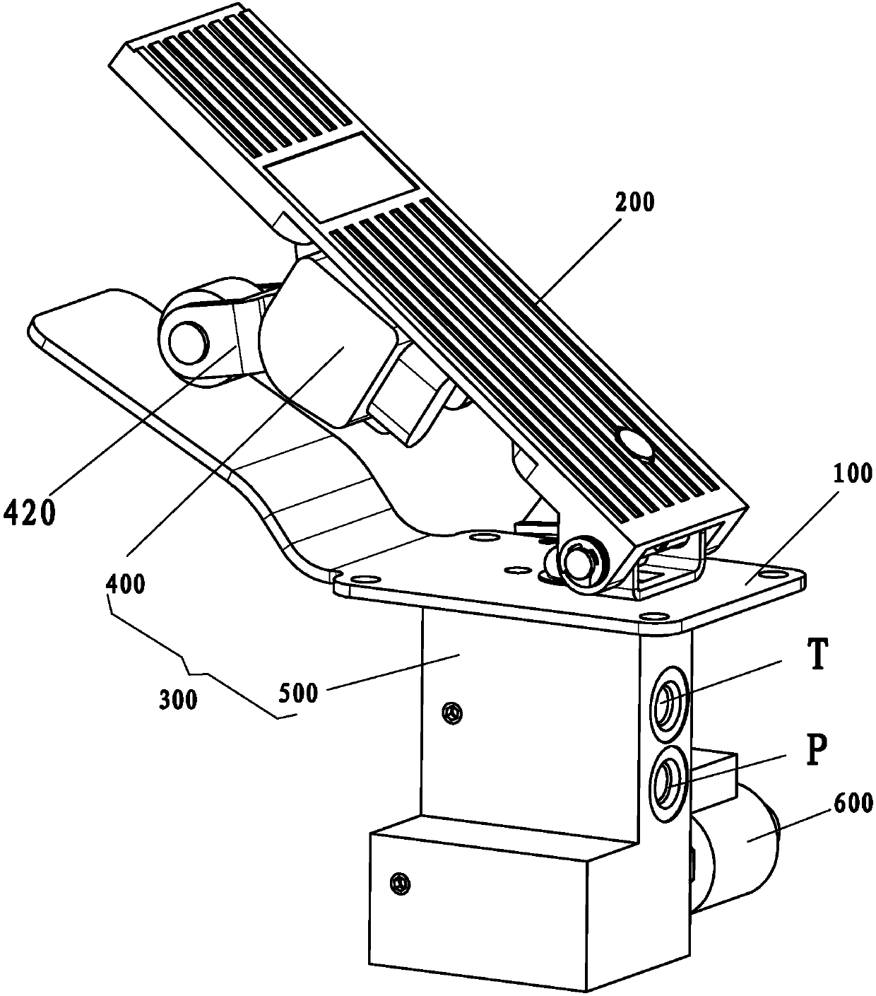
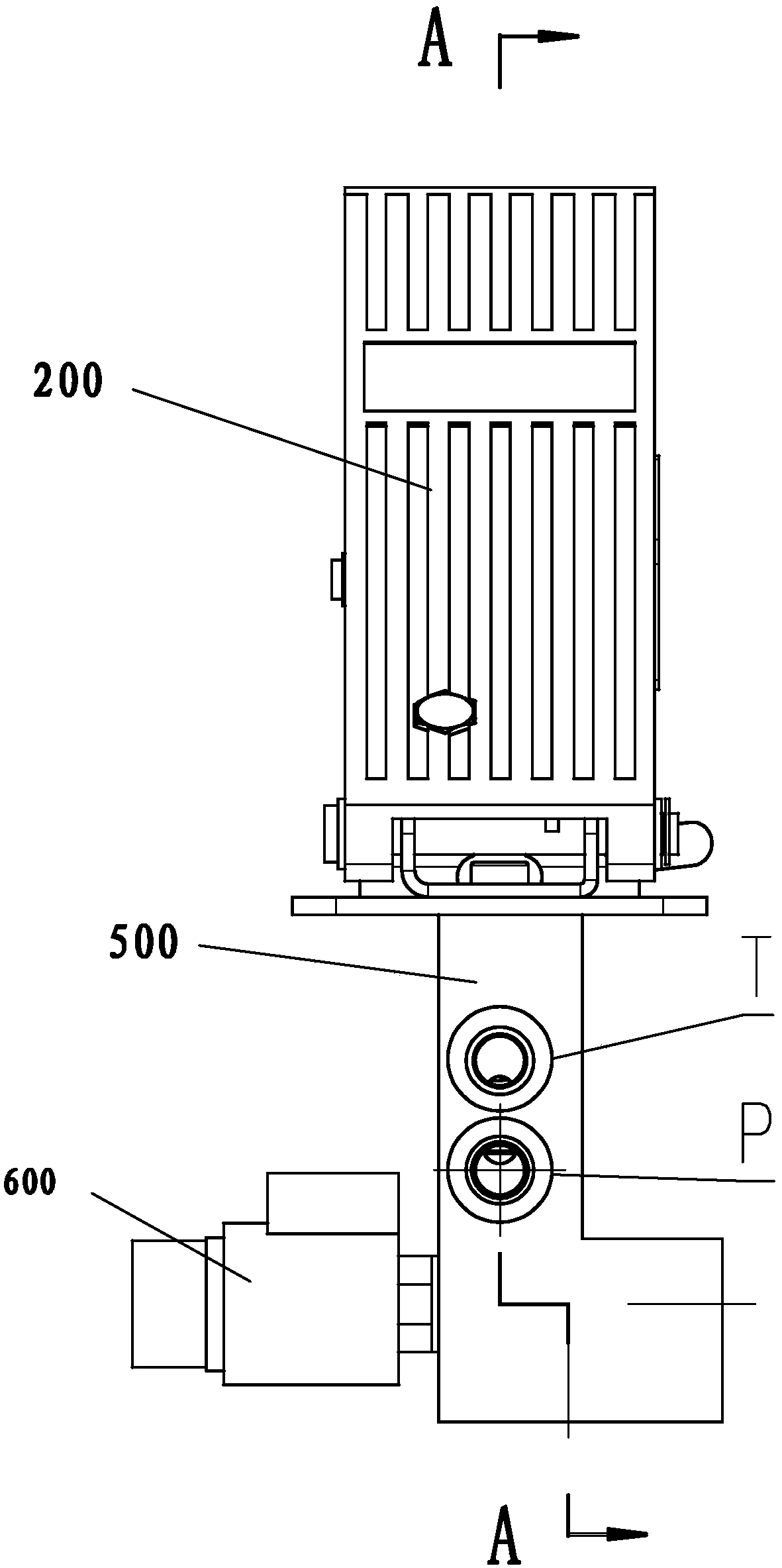
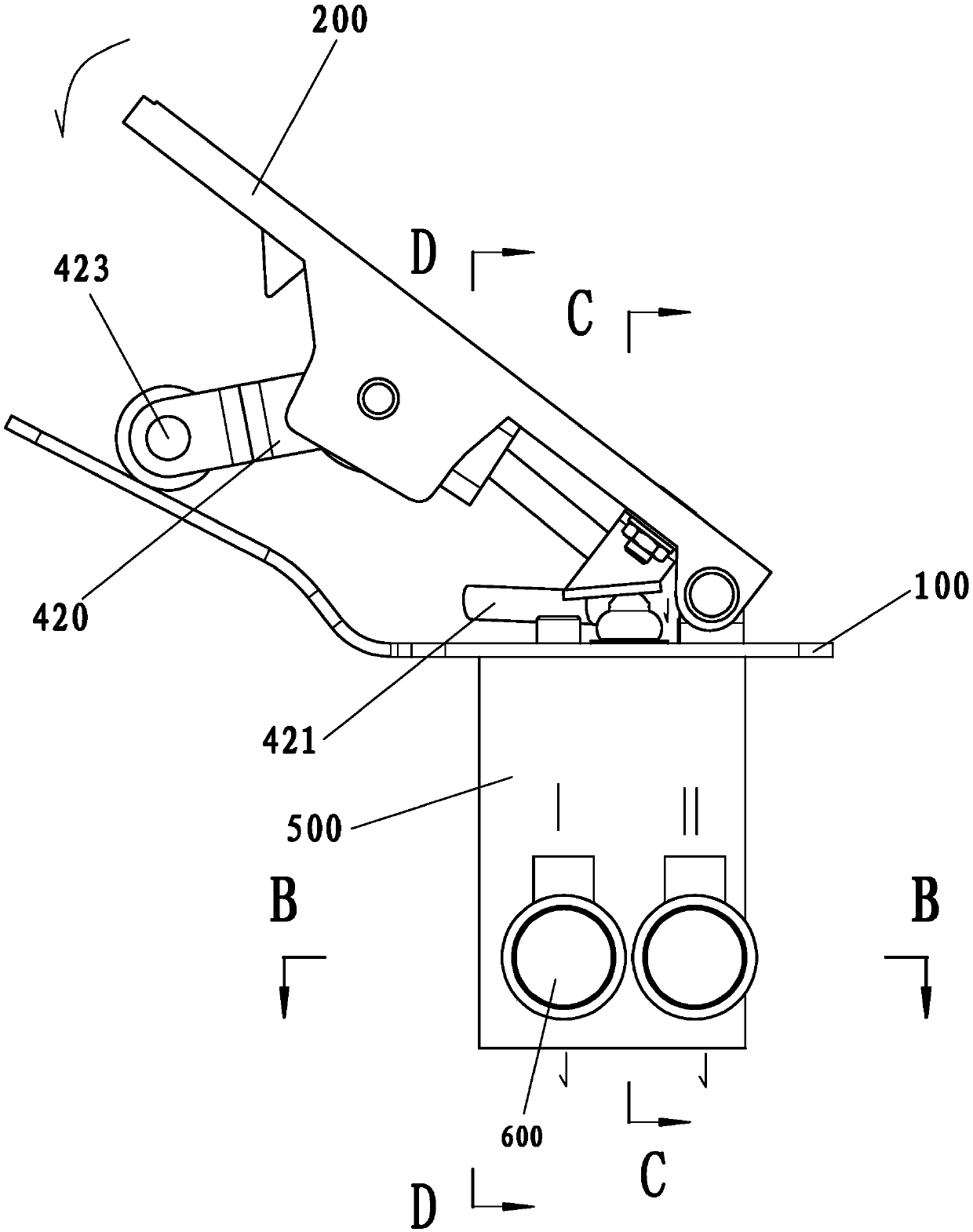
[0052] Such as Figure 1 to Figure 11 As shown, in this embodiment, the combined accelerator and travel control valve assembly mainly includes a pedal mounting seat 100 , a pedal body 200 , and a combined accelerator and travel control valve 300 .

[0053] The throttle and travel control combined valve 300 mainly includes a throttle control device 400 , a travel control combined valve 500 , and a travel direction control solenoid valve 600 .

[0054]The throttle control device 400 mainly includes a reset mechanism and a throttle opening control mechanism 420 .

[0055] The travel control combination valve 500 mainly includes an outer valve body 510 , a combination valve core 512 , a combination return spring 513 and a combination valve control part 514 .

[0056] The traveling direction control solenoid valve 600 mainly includes a solenoid valve body 610, a solenoid valve core 620, an electromagnetic return spring 624 and a solenoid valve control part.

[0057] Preferably, t...

Embodiment 2

[0109] This embodiment also includes an inner valve body 511 , the inner valve body 511 is located in the combined spool chamber 510 b, and the other free end of the outer return spring 5131 pushes against the inner valve body 511 . Through the inner valve body 511, the combination valve oil inlet cavity 510a, the combination valve core cavity 510b, the combination valve distribution cavity 510c and the combination valve oil return cavity 510d can be communicated.

[0110] Preferably, the top of the inner valve body 511 is provided with an inner valve body through hole 5123a adapted to the inner valve core 5122, and the inner valve core lower boss 5122e of the inner valve core 5122 extends into the inner valve body 511, and the inner valve core 5122 The concave part of the inner valve core of the core 5122 and the upper boss 5122d of the inner valve core can freely pass through the through hole 5123a of the inner valve body. When the inner spool 5122 moves down to the working ...


PUM


Abstract

The invention discloses a traveling control pedal assembly. The traveling control pedal assembly comprises a pedal mounting base, a pedal body hinged to the pedal mounting base, a reset mechanism enabling the field angle between the pedal body and the pedal mounting base to reset, and a traveling control combined valve for controlling the forward running and backing speeds. The pedal body controls the traveling control combined valve to cut off a combined valve oil return cavity correspondingly and to communicate with a combined valve division cavity, the flow of hydraulic liquid in the combined valve division cavity and the field angle change in proportion, and the flow of the hydraulic liquid in the combined valve division cavity and the flow of hydraulic liquid communicating with a running correlation mechanism through the traveling control combined valve change in proportion. When a car runs in the acceleration state or deceleration state or other states, the effects that the larger the opening degree of an accelerator is, the more the oil supplied by a hydraulic traveling system is, and the higher the car speed is can be achieved as long as an operator steps on the control part of the combined valve; and meanwhile, the forward running, backing and neutral gear states of the car are achieved by controlling a traveling direction control solenoid valve to be powered on and off; and the more human-friendly control mode can adapt to the driving habits of drivers and operators, and great convenience is brought.

Description

technical field [0001] The invention relates to a pedal of an engineering vehicle such as a wheeled excavator, in particular to an accelerator and travel control combined valve assembly. Background technique [0002] The current engineering vehicles such as wheeled excavators, in the driving state such as driving, parking, acceleration, deceleration, etc., the driver and the operator need to make corresponding operations in time and control the size of the accelerator to adapt to the changes in the driving state. Also need to do corresponding operation to hang gear, adjust steering wheel etc., not only inconvenient to operate, and operability also needs to be further improved. [0003] In the case of complicated road conditions and bad working environment, this brings great inconvenience to drivers and operators, and even affects safe production. [0004] Therefore, in view of the inconvenient operation of engineering vehicles such as wheeled excavators, it is necessary to ...

Claims


Application Information

Patent Timeline
Patent Type & Authority Patents(China)
IPC IPC(8): E02F9/20E02F9/22F15B13/02
CPCE02F9/2004E02F9/2012E02F9/2253E02F9/2267F15B13/02F15B2013/002
Inventor 谢帮亮林秀丹周红梅吴鑫淼
Owner QUANZHOU KINHO CONSTR MACHINERY TECH
Why Eureka
Try Eureka