Step-shaped shrinkage air film hole structure

An air-film hole, step-type technology, which is applied to the supporting elements of the blade, engine elements, machines/engines, etc., can solve the problems of mass flow fluctuation at the outlet of the air film hole and the unfavorable effective coverage of the air film, so as to improve the cooling of the air film. Efficiency, reducing adverse effects, enhancing the effect of feedback

Inactive Publication Date: 2016-12-21
NORTHWESTERN POLYTECHNICAL UNIV
View PDF6 Cites 10 Cited by
  • Summary
  • Abstract
  • Description
  • Claims
  • Application Information

AI Technical Summary

Problems solved by technology

Severe mainstream pressure fluctuations lead to large fluctuations in the mass flow rate at the outlet of the gas film hole, and even alternate flow patterns of reverse flow and forward flow, which are not conducive to the effective coverage of the gas film

Method used


Image

  • Step-shaped shrinkage air film hole structure
  • Step-shaped shrinkage air film hole structure
  • Step-shaped shrinkage air film hole structure

Examples


Embodiment 1

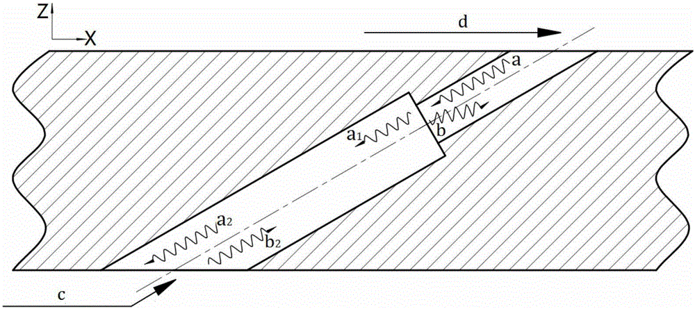
[0027] This embodiment is used to stabilize the outlet flow rate of the air film hole with a stepped shrinking air film hole structure, including a thin cylindrical hole 1 and a thick cylindrical hole 2 . A step shrinkage transition form is applied to the outlet of the single-diameter cylindrical air film hole, and a thin cylindrical hole is connected to form a stepped shrinkable air film hole structure. The step-shaped shrinking air film hole can enhance the feedback effect on the acoustic wave effect, so as to achieve the purpose of correcting the mass flow rate at the outlet of the air film hole and preventing backflow. Among them, the thin cylindrical hole 1 has a flow direction inclination angle α in the X direction, the flow direction inclination angle α=30°, does not have a spanwise inclination angle in the Y axis direction, and the diameter of the thin cylindrical hole 1 is D 1 =0.3mm, the length of the thin cylindrical hole is L 1 =1mm; the thick cylindrical hole 2 h...

Embodiment 2

[0030] This embodiment is used to stabilize the outlet flow rate of the air film hole with a stepped shrinking air film hole structure, including a thin cylindrical hole 1 and a thick cylindrical hole 2 . A step shrinkage transition form is applied to the outlet of the single-diameter cylindrical air film hole, and a thin cylindrical hole is connected to form a stepped shrinkable air film hole structure. The step-shaped shrinking air film hole can enhance the feedback effect on the acoustic wave effect, so as to achieve the purpose of correcting the mass flow rate at the outlet of the air film hole and preventing backflow. Among them, the thin cylindrical hole 1 has a flow direction inclination angle α in the X direction, the flow direction inclination angle α=30°, does not have a spanwise inclination angle in the Y axis direction, and the diameter of the thin cylindrical hole 1 is D 1 =0.3mm, the length of the thin cylindrical hole is L 1 =0.6mm; the thick cylindrical hole 2...


PUM


Abstract

The invention discloses a step-type shrinkage film hole structure, which belongs to the technical field of gas turbine blades; by applying a step-type shrinkage transition form to the outlet of a single-aperture cylindrical gas film hole, a thinner straight hole is connected to form a Step-type shrinking film hole structure that stabilizes the outlet flow rate of the film hole. The step-shaped shrinking air film hole can enhance the feedback effect on the acoustic wave effect, and effectively correct the acoustic wave effect carried by the mainstream pressure fluctuation, so as to achieve the purpose of correcting the mass flow rate of the air film hole outlet and preventing backflow. The step-type shrinkage film hole structure has the characteristics of simple and convenient processing and low cost. Effective use of the film hole structure can greatly improve the stability of the film coverage, improve the film cooling efficiency of high-temperature components of the gas turbine, and improve the working reliability and life of the turbine blades and casing.

Description

technical field [0001] The invention relates to the technical field of gas turbine blades, in particular to a stepped shrinkage film hole structure for stabilizing the outlet flow rate of the film holes. technical background [0002] With the rapid development of aero-engines, the turbine inlet temperature continues to increase, and the turbine inlet temperature of a first-stage engine with a thrust-to-weight ratio of 10 has reached 1900K-2000K, which has far exceeded the heat resistance limit of turbine blade materials. Air film cooling is a cooling technology applied to the blades of gas turbines, that is, the high-pressure cold air is extracted from the last stage of the compressor and transported to the inner channel of the blade. The air film hole is sprayed out, and the cold air bends downstream under the action of the mainstream and the fluid Coanda effect, and adheres to the wall surface to form a cold air film with a lower temperature, which isolates the wall surfac...

Claims


Application Information

Patent Timeline
Patent Type & Authority Applications(China)
IPC IPC(8): F01D5/18
CPCF01D5/186
Inventor 朱惠人钱鑫段佳家魏建生孟通刘聪郭志中
Owner NORTHWESTERN POLYTECHNICAL UNIV
Why Eureka
Try Eureka