

Pneumatic type wave energy power generation device
A power generation device and wave energy technology, which is applied to ocean energy power generation, engine components, machines/engines, etc., can solve problems such as inability to use large-scale power generation
Active Publication Date: 2016-12-21
济南海川投资集团有限公司
View PDF6 Cites 5 Cited by
- Summary
- Abstract
- Description
- Claims
- Application Information
AI Technical Summary
Problems solved by technology
[0002] The currently used or applied patents for ocean wave power generation devices are only suitable for small-scale power generation and cannot be used for large-scale power generation
Method used
View moreImage
Smart ImageViewing Examples

Examples
Embodiment Construction
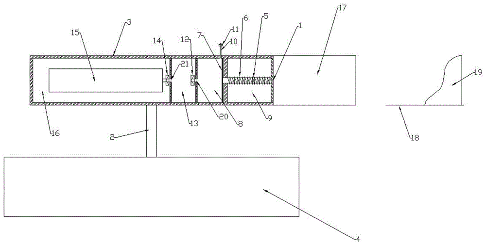
[0008] The content of the invention has described the specific embodiment of the present invention in detail, will not repeat here, need explain: 1. because the time and the energy of each impact push plate 1 of sea wave are not exactly the same, so the pneumatic cylinder 8 will be different pressure every time The compressed air is sent into the energy storage chamber 13 for storage, and then the constant pressure valve 14 releases the compressed air at equal pressure, so as to ensure that the air velocity and flow rate blowing to the rotor of the generator set 15 remain unchanged.
Login to View More PUM
 Abstract
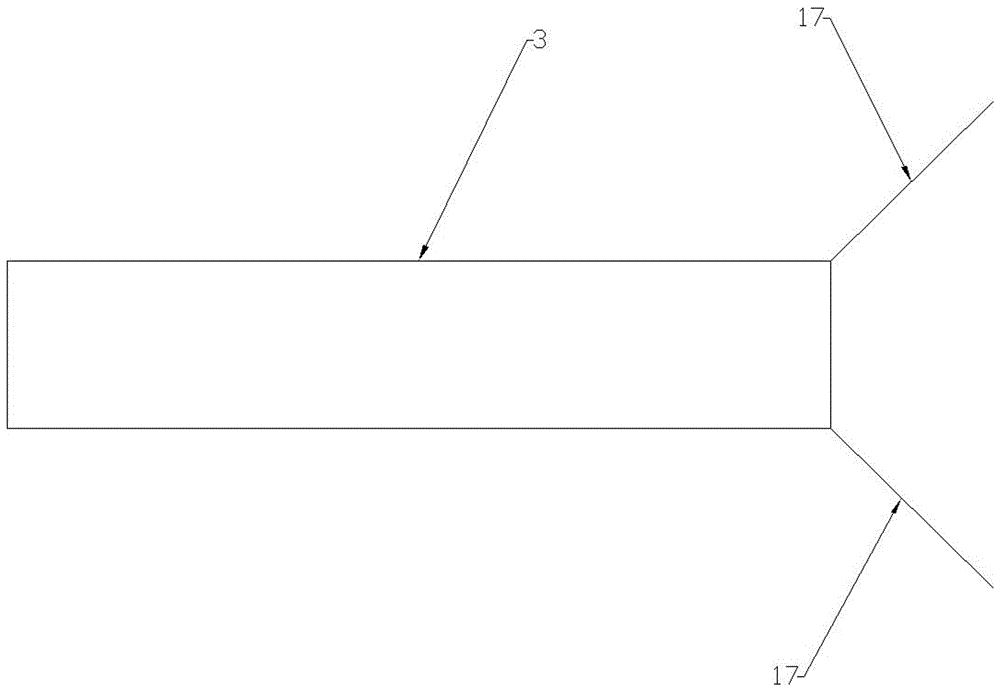
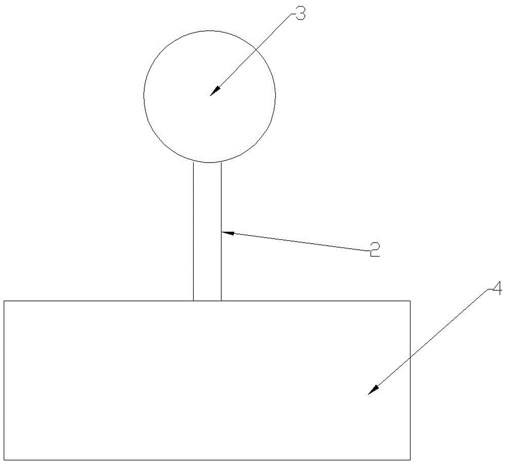
The invention provides a pneumatic type wave energy power generation device which is mainly used for ocean wave energy power generation. According to the pneumatic type wave energy power generation device, large-scale power generation can be achieved, the quantity of generated power is stable, and the power generation device can be directly connected to the national power grid. The pneumatic type wave energy power generation device is mainly composed of a pushing plate 1, a rotating rod 2, a shell 3, a floating box 4, a pushing rod 5, a spring 6, a piston 7, a pneumatic cylinder 8, a pushing chamber 9, an air inlet pipe 10, an air inlet one-way valve 11, a one-way valve 12, an energy storage chamber 13, a constant pressure valve 14, a generator set 15, a generator chamber 16, a deflector 17, a hole A 20 and a hole B 21. The main operating principle of the pneumatic type wave energy power generation device is that sea waves impact the pushing plate 1 to move to the left, the pushing plate 1 pushes the piston 7 to move to the left through the pushing rod 5 so that air in the pneumatic cylinder 8 can be compressed and fed into the energy storage chamber 13, and the compressed air in the energy storage chamber 13 is subjected to equal-pressure releasing through the constant pressure valve 14 to blow a rotor of the generator set 15 to rotate, so that a generator generates power.
Description
technical field [0001] The invention is mainly used for ocean wave power generation. Background technique [0002] The currently used or applied patents for ocean wave power generation devices are only suitable for small-scale power generation and cannot be used for large-scale power generation. Contents of the invention [0003] The invention can generate electricity on a large scale and the electricity generated is stable, and can be directly connected to the national grid; 5), spring (6), piston (7), pneumatic cylinder (8), push chamber (9), intake pipe (10), intake check valve (11), check valve (12), energy storage chamber (13), constant pressure valve (14), generator set (15), generator chamber (16), deflector (17), hole A (20), hole B (21); spring (6) one end and The push plate (1) is fixed, the other end of the spring (6) is fixed to the right side of the push chamber (9); the push rod (5) passes through the spring (6), its right end is fixed to the push plate (1)...
Claims
Login to View More Application Information
Patent Timeline
 Patent Type & Authority Applications(China)
IPC IPC(8): F03B13/24
CPCF03B13/24Y02E10/30
Inventor 彭宝安
Owner 济南海川投资集团有限公司