Radial cage for bearings having high rotational speeds

A cage, axial technology, used in bearings, bearing components, roller bearings, etc., can solve the problems of shortening life, tearing of lubricating film, increasing friction, etc., to increase wear, optimize guiding effect, and improve reliability. sexual effect

Active Publication Date: 2016-12-21
AB SKF
View PDF6 Cites 1 Cited by
  • Summary
  • Abstract
  • Description
  • Claims
  • Application Information

AI Technical Summary

Problems solved by technology

This deformation in turn leads to contact between the radial cage and the needle rollers, resulting in increased friction and tearing of the lubricating film
This can greatly reduce the fatigue strength of the bearing and shorten its life
Also, due

Method used


Image

  • Radial cage for bearings having high rotational speeds
  • Radial cage for bearings having high rotational speeds
  • Radial cage for bearings having high rotational speeds

Examples


Embodiment Construction

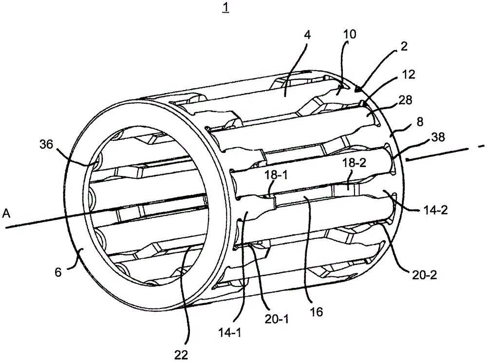
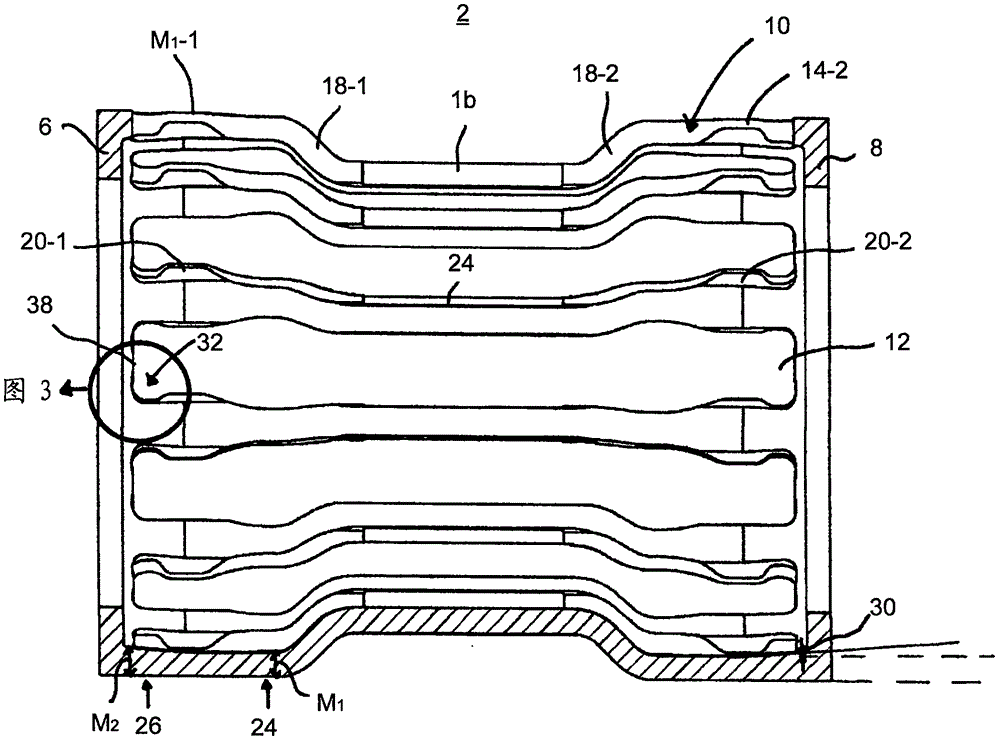
[0021] figure 1 A perspective view of a needle roller cage assembly 1 is shown, comprising a radial cage 2 and a roller 4 inside the radial cage. The radial cage 2 also has a first side ring and a second side ring 6, 8, which have a certain distance in the axial direction and are connected to each other by an axial beam 10, between which there is a space for accommodating the rollers 4. 12 pocket holes. remove figure 1 In addition to figure 2 It can be seen that the axial cross member 10 itself has side sections 14 - 1 , 14 - 2 which are respectively connected to the side rings 6 , 8 . In addition, the axial cross member 10 has a central section 16 which is connected to the side sections 14-1, 14-2 via lateral connection sections 18-1, 18-2. Wherein the side sections 14 - 1 , 14 - 2 and the middle section 16 are axial, and the connecting sections 18 - 1 , 18 - 2 are inclined to the rotation axis A of the bearing 1 .

[0022] The limit flanges 20, 22 installed on the side...


PUM


Abstract

The present disclosure is directed to a radial cage (2) for receiving and guiding cylindrical rolling elements (4), in particular to a needle roller cage. The radial cage includes at least two side rings (6; 8) axially spaced from each other and defining an axial extension of the radial cage (2), and a plurality of axial bridges (10) connecting the side rings to each other. A plurality of pockets (12) for receiving the cylindrical rolling elements (4) is formed between the axial bridges, and the axial bridges (10) each include two side sections (14) connected to the side rings (6; 8) and extending essentially parallel to the axial extension and a center section (16) extending substantially parallel to the axial extension. The center section (16) is connected to the side sections (14) via two connection sections (18). At least one side section (14) includes a first region (24) having a first material thickness (M1) and a second region (26) having a second material thickness (M2) greater than the first material thickness (M1).

Description

technical field [0001] The invention relates to a radial cage for receiving and guiding cylindrical rollers, in particular a needle roller cage. Background technique [0002] Radial cage needle roller cage assemblies or needle roller cages are especially suitable for high-speed applications, such as often used in planetary gears, which place higher demands on the needle roller cage assemblies used due to their high rotational speed. Such needle roller and cage assemblies generally consist of a radial cage and a plurality of needle rollers located in the radial cage and are characterized in particular by a very low radial overall height. At the same time, the needle roller cage assembly can withstand large centrifugal force and acceleration force, so it has high load capacity and circumferential rolling accuracy. [0003] In addition, the radial cage of this type of needle roller and cage assembly consists of two side rings defined by the circumferential extension of the rad...

Claims


Application Information

Patent Timeline
IPC IPC(8): F16C33/46
CPCF16C33/46F16C2300/22F16C33/4623F16C33/4676F16C2240/30F16C19/26F16C33/467
Inventor D·斯特布劳
Owner AB SKF
Why Eureka
Try Eureka