Driving belt

A technology of transmission belt and rubber layer, which is applied in the field of transmission belt

Active Publication Date: 2016-12-21
GATES UNITTA POWER TRANSMISSION (SUZHOU) LIMITED
View PDF10 Cites 0 Cited by
  • Summary
  • Abstract
  • Description
  • Claims
  • Application Information

AI Technical Summary

Problems solved by technology

[0005] The present invention mainly aims at the above-mentioned existing technical problems and makes further improvements. It provides a transmission belt with a fabric on the back and the fabric is sewn with sutures, and the surface of the fabric has a raised pattern structure rubber. The sutures of the transmission belt are patterned The structural rubber is covered without leakage, the appearance of the transmission belt is good, and it can further reduce or solve the problem of the wear of the suture and the periodic noise caused by the contact between the pulley and the suture during the operation of the transmission belt

Method used


Image

  • Driving belt
  • Driving belt
  • Driving belt

Examples


Embodiment Construction

[0024] The specific embodiments of the present invention will be further described below with reference to the accompanying drawings.

[0025] The drive belt of the present invention is an example of a V-belt, but it is not limited thereto, it can also be a synchronous belt or a V-belt.

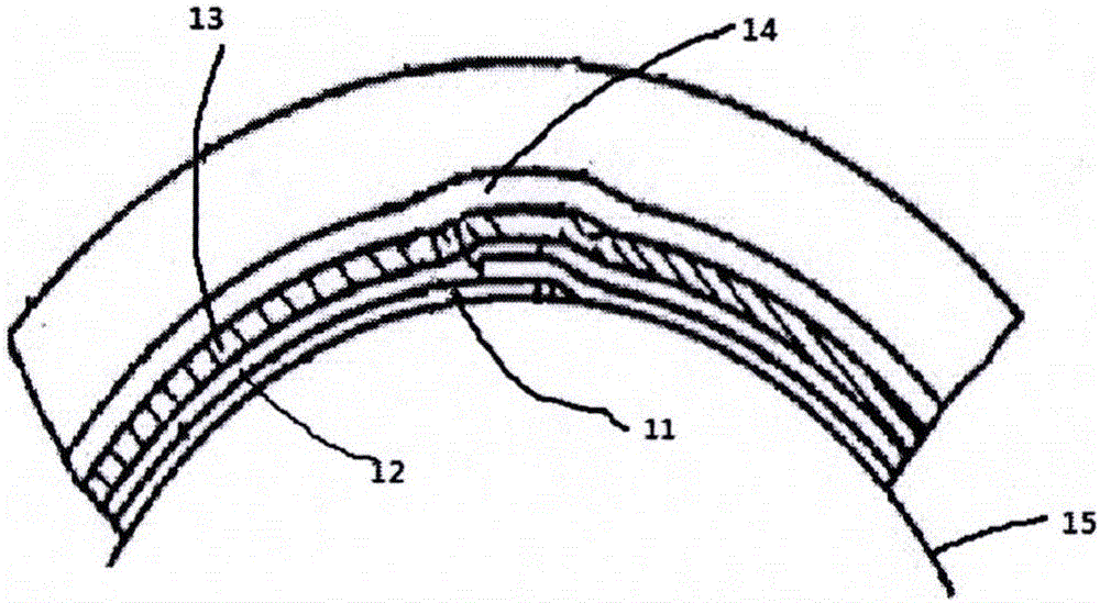
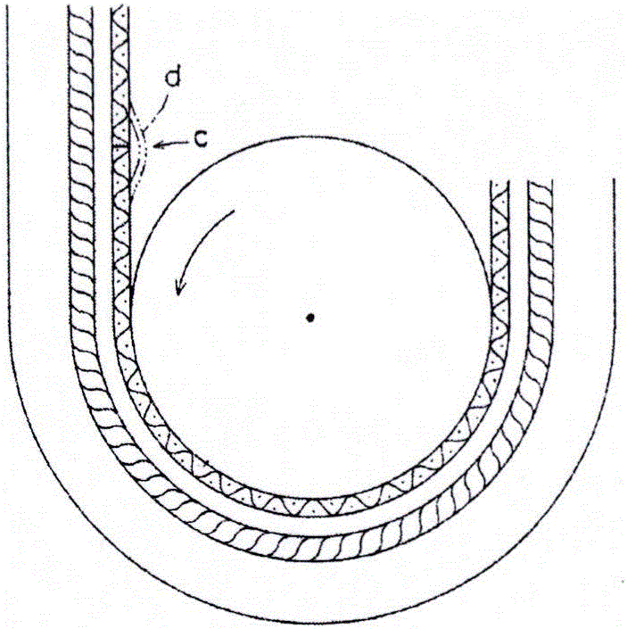
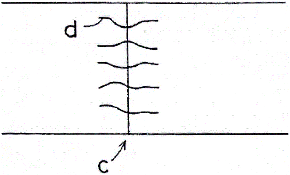
[0026] Such as Figure 4 The V-ribbed belt shown comprises a bottom rubber layer 1, an adhesive rubber layer 5, a tensile cord 2 embedded in the adhesive rubber layer and a back fabric layer 4 bonded to the back of the adhesive rubber layer 5, as image 3 As shown, the fabric layer has a butt joint c sewn with stitching d, and the bottom rubber layer 1 has at least one rib extending along the length of the belt.

[0027] The rubber of the bottom rubber layer and the adhesive rubber layer can be made of the same rubber or different rubbers, and the rubber layer can be made of, for example, hydrogenated nitrile rubber, chloroprene rubber, EPDM rubber, etc. in the prior art. Or several kinds o...


PUM

PropertyMeasurementUnit
Heightaaaaaaaaaa
Heightaaaaaaaaaa

Abstract

The inventions provides a driving belt. A fabric layer covers on the back of the driving belt; the fabric layer is provided with a butt joint sewn by threads; the outer surface of the fabric layer is projecting pattern structure rubber, the threads are covered in the projecting pattern structure rubber. Compared with the traditional driving belt with fabric on the back, the driving belt with the structure has better appearance, and the noise is relieved further.

Description

Technical field: [0001] The present invention relates to drive belts, especially drive belts with a fabric back. Background technique: [0002] With the continuous improvement of human living standards, the automobile market is also developing and growing with each passing day, and the requirements for stability and comfort are getting higher and higher. Higher and higher. [0003] Early power transmission belts such as figure 1 As shown, the fabric 11, rubber 12, tensile cord 13, and rubber 14 are wound on the mold 15 as required to form a rubber sleeve, and then the rubber sleeve is vulcanized, and the vulcanized rubber sleeve is cut into a predetermined width according to various sizes. Transmission belt. The fabric 11 is wound on the cylindrical mold 15, and will form a joint on the outer surface of the mold that is roughly parallel to the axis of the cylindrical mold. At this joint, there will be an overlap of a certain width, causing the tensile cords to not be on t...

Claims


Application Information

Patent Timeline
IPC IPC(8): F16G5/04
CPCF16G5/04
Inventor 高敏段让明
Owner GATES UNITTA POWER TRANSMISSION (SUZHOU) LIMITED
Why Eureka
Try Eureka