

A kind of automatic control method for incinerator feeding
An incinerator and control system technology, applied in the direction of combustion method, incinerator, combustion type, etc., can solve problems such as fluctuations in cement production process, fire, combustion outside the garbage furnace, etc., to prevent equipment and personal injury and reduce system risk , the effect of improving safety
- Summary
- Abstract
- Description
- Claims
- Application Information
AI Technical Summary
Problems solved by technology
Method used
Image

Examples
Embodiment Construction
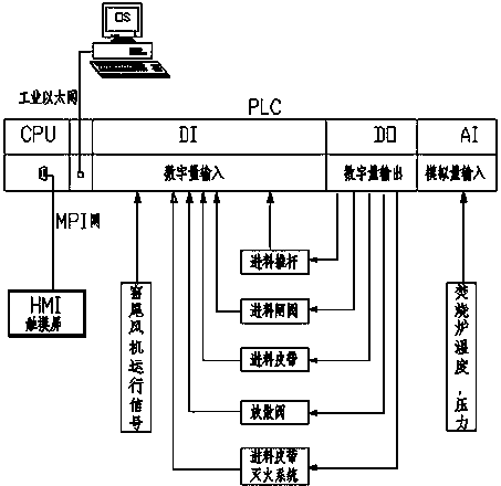
[0019] An automatic control method for incinerator feed, including a feed push rod control system and a feed gate valve control system, when the feed gate valve control system controls the feed gate valve to open, the feed push rod control system controls the feed push rod Reciprocating push material, adjust the reciprocating operation time interval of the feed push rod according to the amount of incoming material at the feed port of the incinerator and the temperature and pressure of the incinerator, set the time interval t of the feed push rod action, and the running speed of the feed belt V, The temperature of the incinerator is T, the pressure is P, k 1 ,K 2 is the proportional coefficient, the push rod movement interval time can be expressed by formula (1):
[0020] (1)
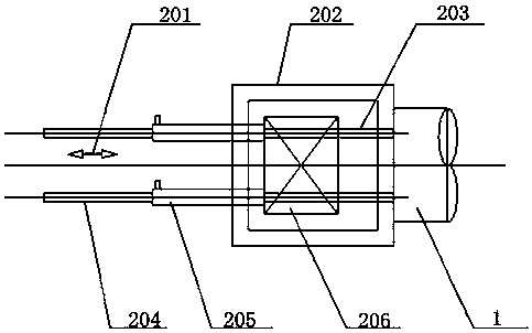
[0021] to combine figure 1 The feed push rod is composed of a push rod, a hydraulic cylinder, a push head, and a push head guide rail. When working, the hydraulic cylinder drives the push rod to co...
PUM
 Abstract
Description
Claims
Application Information