
Fuel composition

a technology of fuel composition and composition, applied in the direction of gaseous fuels, fuels, mechanical equipment, etc., can solve the problems of easy ignition, excessive ignition delay time, and inability to use pure methane in compression ignition engines of the day, so as to reduce the need for external energy input, reduce the effect of autoignition delay time and fast ignition

Pending Publication Date: 2022-09-22
SHELL OIL CO
View PDF0 Cites 0 Cited by
  • Summary
  • Abstract
  • Description
  • Claims
  • Application Information

AI Technical Summary

Benefits of technology

The present invention relates to a new fuel composition that can be used in combustion engines. This fuel composition is made by adding an ignition improving additive to liquefied methane, which results in a more efficient and effective fuel. The fuel composition has improved properties such as lower autoignition temperature, faster ignition, and reduced external energy input for ignition. In addition, this fuel can also improve lubricity, energy density, and keep engines and fuel systems clean. Overall, this invention provides a more powerful and efficient way to fuel combustion engines.

Problems solved by technology

While methane provides a high mass-specific energy content (about 15% higher than gasoline and diesel), it is not easy to ignite and therefore pure methane cannot be used in today's compression ignition engines used in energy efficient vehicles (trucks, ships, locomotives, and the like, as mentioned above).
This is because self-ignition of methane happens at too high a temperature and the ignition delay times are too long.
This engine type needs a complex injection system, two fuel systems and more complex controls while not providing less exhaust treatment demand.
This engine type cannot make full use of the potential CO2 advantage of methane because some diesel fuel (pilot diesel) is still necessary.

Method used


Image

  • Fuel composition
  • Fuel composition
  • Fuel composition

Examples


examples 1-15 (

Autoignition Experiments)

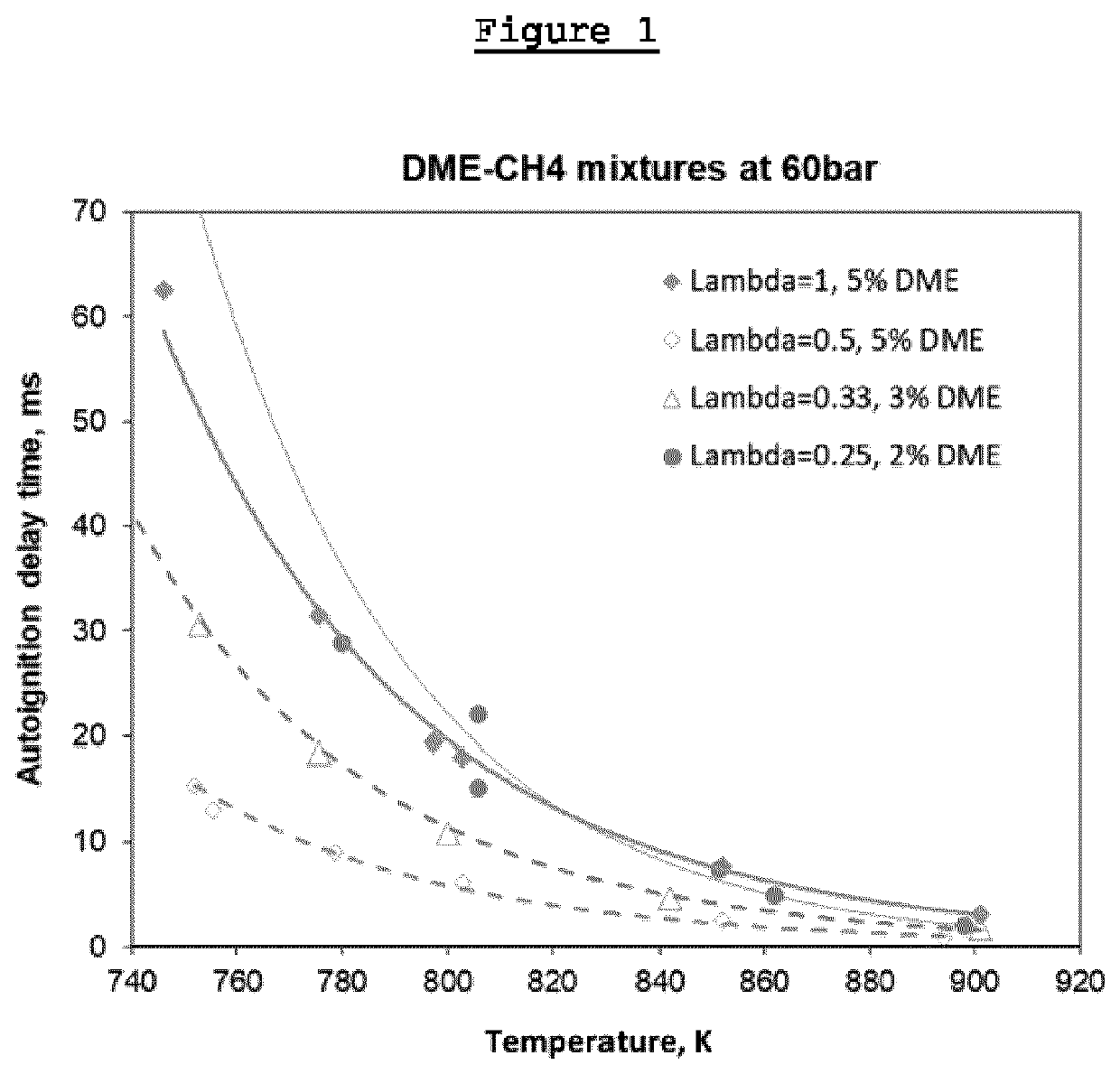
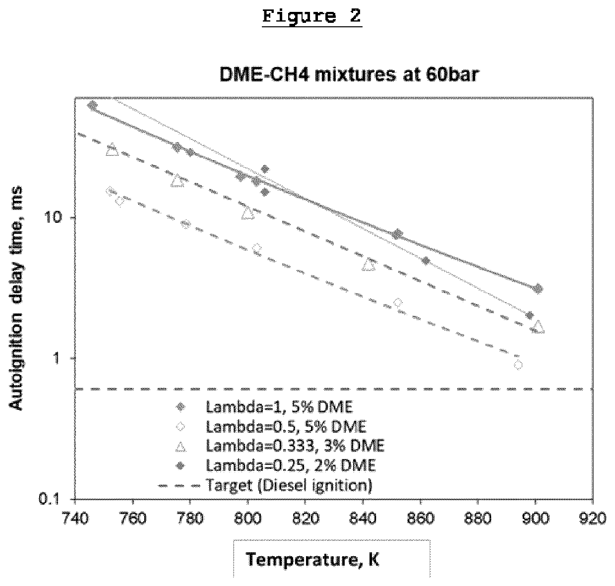
[0070]Fuel compositions were prepared by blending pure methane with dimethylether (DME) in amounts as shown in Table 1 below.

TABLE 1ExampleAdditiveVol % of additiveVol % of methane1DME595%2DME397%3DME298%

[0071]Autoignition experiments were performed on the fuel compositions shown in Table 1 using a rapid compression machine. The experimental conditions were as follows:

[0072]Pressure: 60 bar

[0073]Temperature: 750-900 K

[0074]Fuel / air ratio, λ:1.0, 0.5, 0.33, 0.25

[0075]FIGS. 1 and 2 are plots that show the autoignition delay time versus the temperature for each of Examples 1-3.

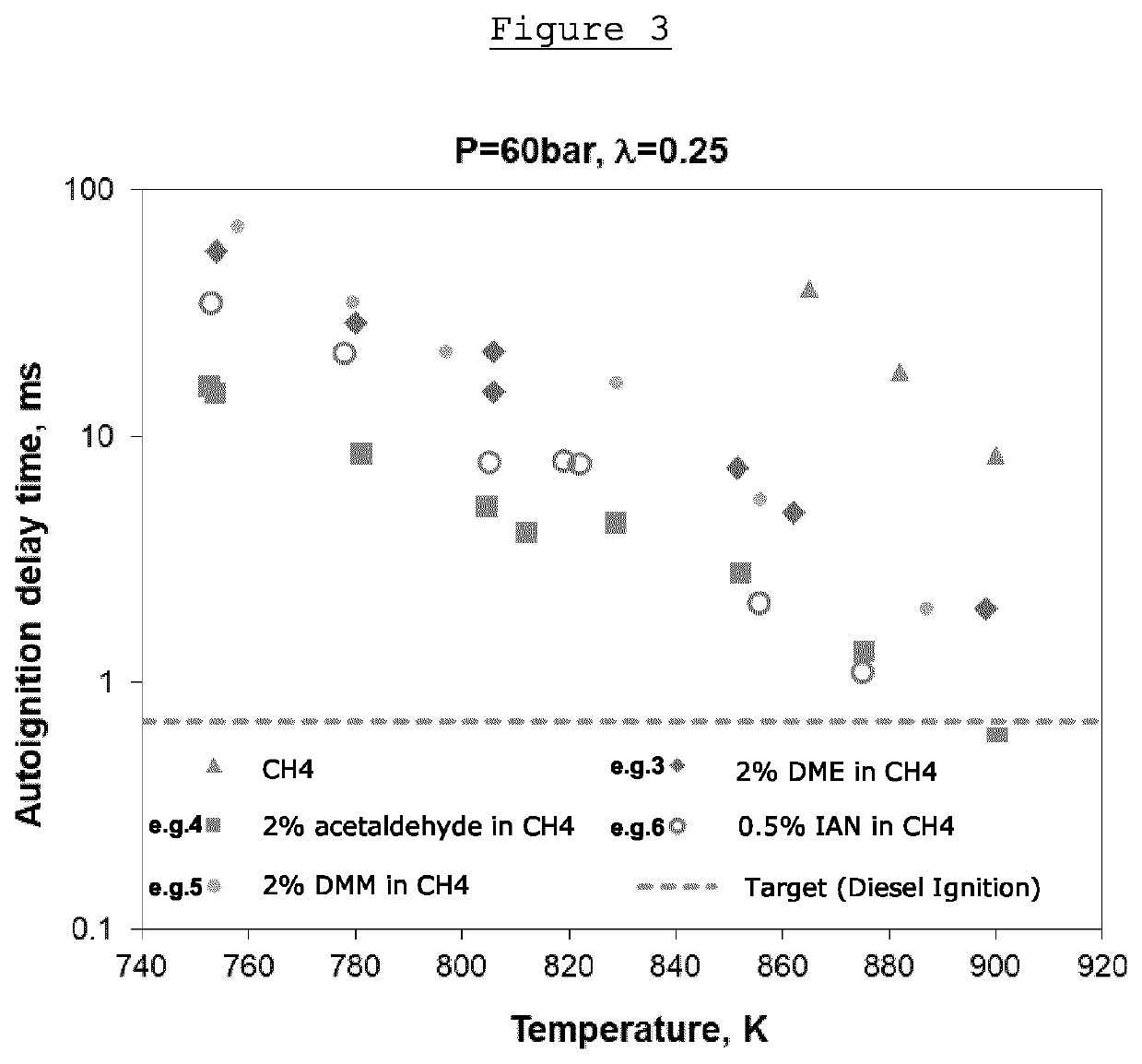
[0076]Further fuel compositions were prepared by blending pure methane with acetaldehyde, dimethoxymethane (DMM) and iso-amyl nitrite (IAN) in amounts as shown in Table 2 below.

TABLE 2ExampleAdditiveVol % of additiveVol % of methane4Acetaldehyde2985DMM2986IAN0.599.5

[0077]Autoignition experiments were performed on the different fuel compositions shown in Table 2 using a rapid compression m...


PUM

PropertyMeasurementUnit
autoignition temperatureaaaaaaaaaa
boiling pointaaaaaaaaaa

Abstract

A fuel composition wherein the fuel composition comprises (a) a major amount of liquefied methane based gas in cryogenic state having a temperature in the range from −182° C. to −100° C. and, preferably, a pressure in the range of 1 bar to 15 bar, and (b) a minor amount of an 5 ignition improving additive, wherein the ignition improving additive has a melting point of less than −105° C., a boiling point of less than 60° C. and an autoignition temperature of lower than 480° C. and wherein the ignition improving additive is selected from alkanes, alkenes, alcohols, ethers, alkynes, aldehydes, ketones, amides, nitroalkanes, nitrosoalkanes, nitrates, nitrites, cycloalkanes, cycloalkenes, dienes, peroxides, triatomic oxygen, trimethylamine, ethylene oxide, propylene oxide, and mixtures thereof.

Description

FIELD OF THE INVENTION[0001]The present invention relates to a fuel composition and in particular, to a liquefied fuel composition comprising liquefied methane based gas in a cryogenic state which is suitable for use in an internal combustion engine, especially a compression ignition internal combustion engine. The present invention also relates to a process for producing said liquefied fuel composition.BACKGROUND OF THE INVENTION[0002]Natural gas, consisting mainly of methane, has a significant CO2 advantage over crude oil based fuels and burns more cleanly. Even higher CO2 advantages are provided by methane from biogas production (biomethane) and from power-to-gas (power-to-methane) plants. This renewable methane production is attractive as it could be done with higher efficiency compared to other renewable fuel production pathways.[0003]When it comes to the use of methane as fuel for mobility and transport, methane gas must be converted into a storable form. Liquefaction of metha...

Claims


Application Information

Patent Timeline
Patent Type & Authority Applications(United States)
IPC IPC(8): C10L1/185C10L3/06C10L10/00C10L1/02
CPCC10L1/1852C10L3/06C10L10/00C10L1/026C10L2270/026C10L2230/22Y02T10/30
Inventor KOOT, MATTHIJS PIETERLEVINSKY, HOWARD BARRETTGERSEN, SANDERVAN ESSEN, VINCENT MARTIJNKOFOD, MAX BERNHARD FRIEDRICHSLEESWIJK VISSER, FENNA IONAVAN DIJK, GERARDUS HUGO JOZEF
Owner SHELL OIL CO
Learn More