Pulse vector high-pressure burner

A burner and pulse technology, applied in the direction of burner, lighting and heating equipment, etc., can solve the problems of complex structure and high operating cost, and achieve the effect of high thermal efficiency, low cost and stable working conditions

Inactive Publication Date: 2008-10-01
ZEROQ SCI & TECH
View PDF0 Cites 10 Cited by
  • Summary
  • Abstract
  • Description
  • Claims
  • Application Information

AI Technical Summary

Problems solved by technology

The existing technology has the disadvantages of complex structure and high operating cost

Method used


Image

  • Pulse vector high-pressure burner
  • Pulse vector high-pressure burner
  • Pulse vector high-pressure burner

Examples


Embodiment 1

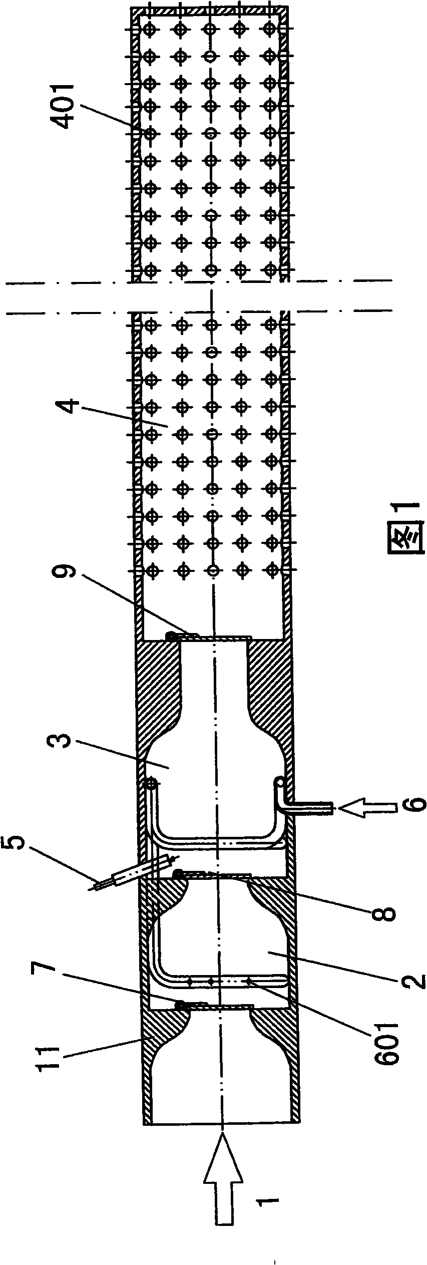
[0033] The structure of the device for automatically generating pulsed supply of oil and gas by utilizing gas and oil pressure changes is as follows: the fuel oil inlet pipe 6 leads into the inner chamber of the combustion chamber 3 and the oil-gas mixing chamber 2, and the fuel oil inlet pipe 6 has a plurality of An oil mist spray hole 601, the oil-gas mixing chamber 2, the combustion chamber 3, and the flame injection pipe 4 have a combined housing 11 connected to each other, and between the oil-gas mixing chamber 2 and the high-pressure air, there is only a direction toward the flame injection pipe 4. The No. 1 check valve 7 that can't get in and out is provided between the combustion chamber 3 and the oil-gas mixing chamber 2, and the No. 2 check valve 8 that can only go out in the direction of the flame injection pipe 4 is provided between the combustion chamber 3 and the flame injection A No. 3 check valve 9 is provided between the pipes 4 toward the direction of the flam...

Embodiment 2

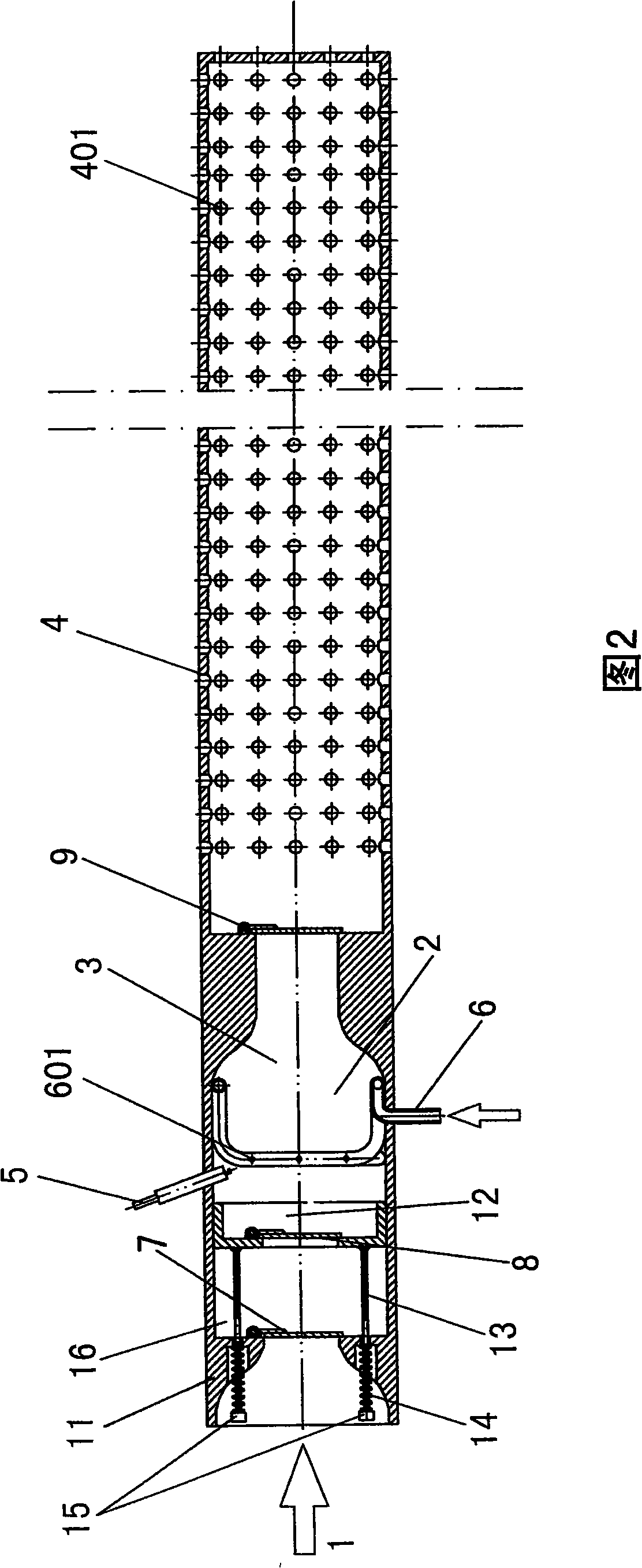
[0043]Please refer to Fig. 2, the structure of the device for automatically generating pulsed supply of oil and gas by using gas and oil pressure changes is as follows: the fuel oil inlet pipe 6 leads into the inner cavity of the combustion chamber 3 and the oil-gas mixing chamber 2, and the fuel oil inlet pipe 6 There are a plurality of oil mist spray holes 601 on the pipe wall. The oil-gas mixing chamber 2, the combustion chamber 3 and the flame injection pipe 4 have a combined housing 11 connected to each other. A slide valve 12 with a hole in the center is arranged in the oil-gas mixing chamber 2. , the slide valve 12 touches at least two guide rods 13, and the extended end of the guide rods 13 protruding from the air compression chamber 16 is set with a return spring 14, and the spring 14 is limited by the counterweight 15 at the end of the guide rod 13 , between the pressurized air 1 and the air compression chamber 16, there is a No. 1 one-way valve 7 that can only go in ...

Embodiment 3

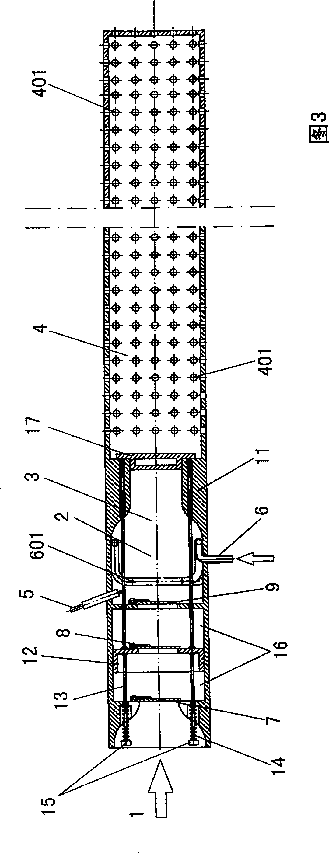
[0057] Please refer to Fig. 3, the structure of the device for automatically generating pulse supply of oil and gas by using gas and oil pressure changes is as follows: the fuel oil inlet pipe 6 leads into the inner cavity of the combustion chamber 3 and the oil-gas mixing chamber 2, and the fuel oil inlet pipe 6 There are a plurality of oil mist spray holes 601 on the pipe wall, the oil-gas mixing chamber 2, the combustion chamber 3, and the flame injection pipe 4 have a combined housing 11 connected to each other, and a slide valve with a hole in the center is arranged in the air compression chamber 16 12. There is a normally closed valve cover 17 in the pipe hole between the combustion chamber 3 and the flame injection pipe 4. The valve cover 17 is connected to at least two guide rods 13, and the guide rods 13 pass through the slide valve 12. The guide rods Fixed on the slide valve 12, the extended end of the guide rod protruding from the combination housing 11 is set with a...


PUM


Abstract

A pulse vector high pressure burner is composed of an air compression part, an oil and gas mixing chamber part, a combustion chamber part and a flame jet pipe communicated with each other in turn. The cavity of the combustion chamber is connected with a fuel sucker, a spark plug; the tube wall of the flame jet pipe is densely covered with a flame jet; the air compression part, the oil and gas mixing chamber part, the combustion chamber part are provided with a device composed of a check valve using the gas and oil pressure change to generate the pulse to supply air, wherein the device has 3-4 groups of check valves, except a group of check valves toward the flame jet pipe direction at the pressure entrance just in not out, the directions of the others just out not in; the invention can realize the fast pressurizing heating, large spray pressure, high temperature, good stability, which is suitable for the boimass compression moulding process and the required pressure heating or pressure combustion-supporting process.

Description

technical field [0001] The present invention relates to high pressure flame burners. Background technique [0002] Burners that spray high-pressure flames have a wide range of uses, and one of them is a burner that uses mixed oil and gas as the combustion medium, which can continuously and rapidly high-pressure heating or pressure-assisted combustion. The prior art has the disadvantages of complex structure and high operation cost. Contents of the invention [0003] The present invention provides a pulse vector high-pressure burner, the purpose of which is to realize rapid pressure heating, high injection pressure, high temperature, and good stability, and is suitable for biomass compression molding processes and processes that require pressure heating or pressure combustion. The structure of the present invention is simple , Wide range of uses, easy operation, low cost, high thermal efficiency, stable working conditions. [0004] The purpose of the present invention is ...

Claims


Application Information

Patent Timeline
Patent Type & Authority Applications(China)
IPC IPC(8): F23D11/24F23D11/36
Inventor 靳宇男
Owner ZEROQ SCI & TECH
Why Eureka
Try Eureka