Biomass boiler monitoring system

A biomass boiler and monitoring system technology, applied in lighting and heating equipment, fluid heaters, water heaters, etc., can solve the problems of reduced combustion efficiency, high labor intensity of operators, and low production efficiency.

Inactive Publication Date: 2009-02-11
ZHUHAI HUISHENG ENERGY SOURCE TECH DEV
View PDF0 Cites 10 Cited by
  • Summary
  • Abstract
  • Description
  • Claims
  • Application Information

AI Technical Summary

Problems solved by technology

[0006] In addition, the existing biomass fuel hot water boilers or hot blast stoves need to open the furnace door every time they feed materials. After the furnace door is opened, excess natural air will enter the furnace, thereby reducing the combustion efficiency.
Moreover, each time the material is fed, the pushing block used for pushing the material needs to be manually reciprocated to push the material, and the labor intensity of the operator is high, which makes the production efficiency low

Method used


Image

  • Biomass boiler monitoring system
  • Biomass boiler monitoring system
  • Biomass boiler monitoring system

Examples


Embodiment 1

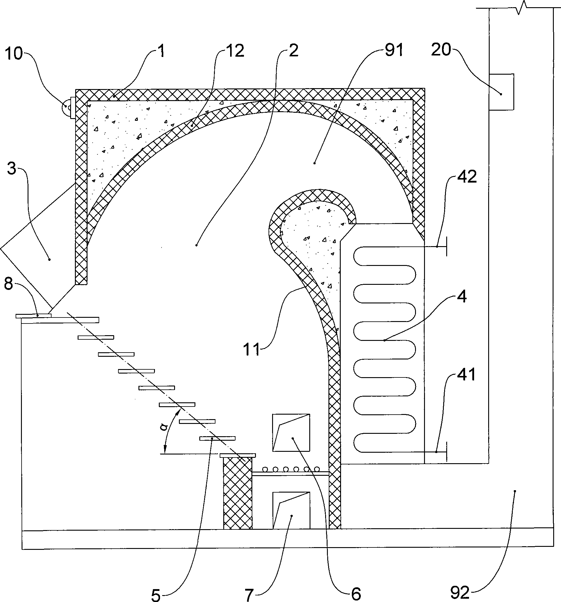
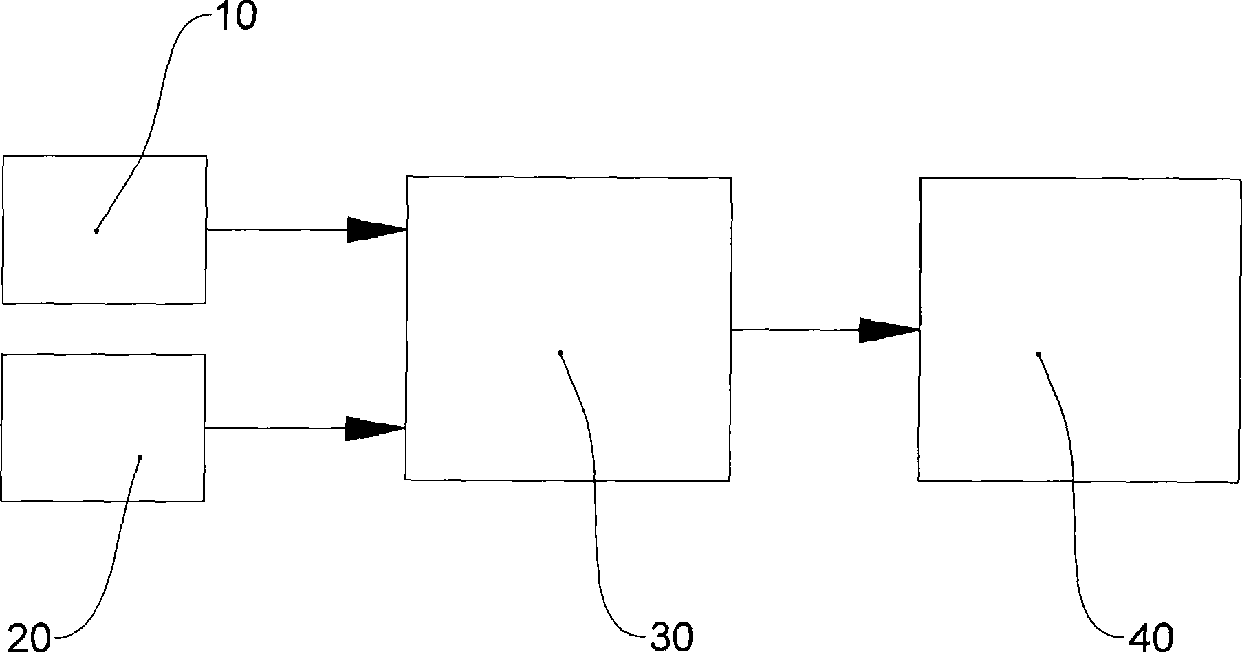
[0026] Such as figure 1 , image 3 As shown, the present invention includes a biomass boiler body and a smoke exhaust channel 92. The biomass boiler body is provided with a camera 10 for monitoring the feed port, and a gas induction monitor 20 is provided in the smoke exhaust channel 92. The camera 10, the gas induction monitor 20 are connected to the signal receiver 30, the signal receiver 30 is connected to the signal recorder 40, and the signal receiver 30 and the signal recorder 40 are placed in the environment Regulatory department, described camera 10, described gas induction monitor 20 are connected with the described signal receiver 30 that is positioned at remote by the wireless network such as GPRS or CDMA, and described signal receiver 30 is positioned at local signal record by wired network Instrument 40 is connected.

[0027] The biomass boiler in this embodiment is a hot water boiler. The biomass boiler body includes a furnace body 1, a furnace 2, a hopper 3, ...

Embodiment 2

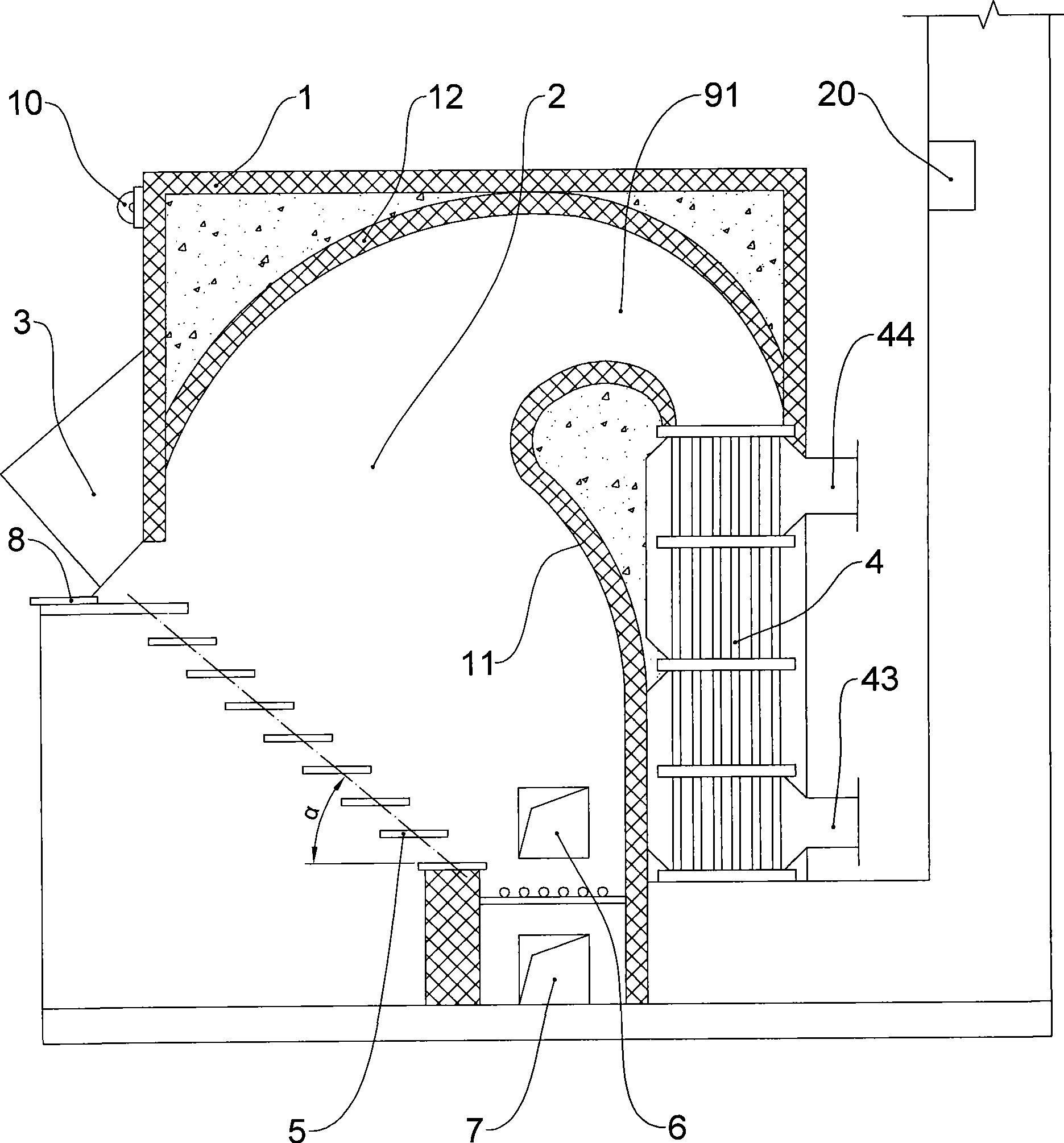
[0030] Such as figure 2 , image 3As shown, the difference between this embodiment and Embodiment 1 is that the biomass boiler in this embodiment is a hot blast stove, the heat exchanger 4 in this embodiment is a gas-gas heat exchanger, and the cooling of the heat exchanger 4 The cold air inlet 43 and the hot air outlet 44 are respectively provided on the two sides, and the hot side of the heat exchanger 4 communicates with the smoke passage 91 and the smoke exhaust passage 92 respectively.

[0031] The present invention monitors the feeding situation of the feed port through the camera 10 at all times, and can accurately identify the type of fuel, thereby preventing coal with high pollution emissions from being used as fuel, and the camera 10 obtains the signal through the signal recorder 40 The real-time image signal of the real-time video signal is recorded for future viewing; meanwhile, the harmful gas in the smoke exhaust channel 92 is monitored in real time through the...


PUM


Abstract

The invention discloses a biomass boiler monitoring system which can monitor the charge and discharge in a real time manner. The biomass boiler monitoring system can ensure that only biomass fuel is used by the biomass boiler to avoid using fuel with high-pollution emission. The biomass boiler monitoring system comprises a biomass boiler body and a smoke evacuation passage (92). The biomass boiler body is equipped with a camera (10) for monitoring a feed port, and the smoke evacuation passage (92) is equipped with a gas induction monitor (20). The camera (10) and the gas induction monitor (20) are connected with a signal receiver (30), and the signal receiver (30) is connected with a signal recorder (40). The biomass boiler monitoring system can be widely applied to the boiler field.

Description

technical field [0001] The invention relates to a biomass boiler monitoring system. Background technique [0002] Hot water boiler is a commonly used thermal energy conversion equipment that uses fuel to burn in the furnace to release chemical energy, and heat low-temperature water to high-temperature water at a certain temperature. Hot water boilers are widely used in industrial and agricultural production and daily life to produce hot water, heating and other fields. Current hot water boilers generally use coal, petroleum, electric energy, etc. as fuel sources. [0003] The hot blast stove is a thermal energy conversion device that uses fuel (coal, oil, natural gas, organic waste, etc.) to burn in the furnace to release chemical energy, and heats low-temperature air to high-temperature air at a certain temperature. The hot stove can also use other thermal energy (electric energy, waste heat) to heat the air. Hot air stoves are widely used in plastics, rubber, chemicals,...

Claims


Application Information

Patent Timeline
Patent Type & Authority Applications(China)
IPC IPC(8): F24H9/20F24H1/00F24H9/18F24H9/00
Inventor 杨奇飞聂民
Owner ZHUHAI HUISHENG ENERGY SOURCE TECH DEV
Why Eureka
Try Eureka