Humidity detection device designed based on IP65 waterproof grade
A humidity detection and humidity detection circuit technology, applied in the detection field, can solve the problems of inaccurate humidity sensors and different indication values, and achieve the effect of improving the running time and life of equipment, reducing ripple content, and ensuring smooth operation.
- Summary
- Abstract
- Description
- Claims
- Application Information
AI Technical Summary
Problems solved by technology
Method used
Image
Examples
Embodiment 1
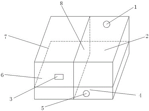
[0036] Humidity detection equipment based on the design of IP65 waterproof level, using the chassis body with IP65 waterproof level to package and integrate the humidity detection circuit, can detect the humidity information of the environment in the case of high waterproof performance, and use the mode of light display real-time broadcast, such as figure 1 , figure 2 As shown, the following structure is particularly arranged: a humidity detection device body is included, a circuit board 7 for installing a humidity detection circuit is arranged inside the humidity detection device body, and the humidity detection device body is divided into a power supply through an isolation plate 8 along the height direction Installation area 6 and humidity detection circuit installation area 2; a switch installation position 3 is arranged on the outer wall of the power supply installation area 6 of the humidity detection equipment body, and a sensor installation is arranged on the outer wa...
Embodiment 2
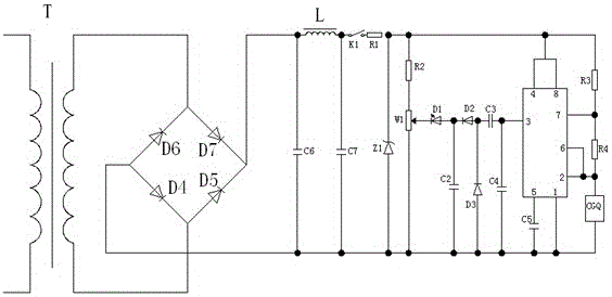
[0039] This embodiment is further optimized on the basis of the above-mentioned embodiments, further to better realize the present invention, such as figure 1 , figure 2 As shown, the following arrangement structure is adopted in particular: the power circuit installed on the circuit board 7 at the power supply installation area 6 and the humidity sensor installed on the circuit board 7 at the humidity detection circuit installation area 2 are arranged in the humidity detection circuit. The detection processing circuit, the speed detection circuit and the integrated heat dissipation component are arranged on the back of the circuit board 7; the power supply circuit is provided with a transformer T, a rectifier circuit and a filter circuit, and the primary end of the transformer T is connected to the 220V AC power supply, and the transformer T The secondary end of the rectification circuit is connected to the AC input end of the rectification circuit, the DC output end of the ...
Embodiment 3
[0042] This embodiment is further optimized on the basis of any of the above embodiments, further to better realize the present invention, such as figure 1 , figure 2 As shown, the following arrangement structure is particularly adopted: a switch K1 and a resistor R1 are arranged in the switch circuit, a voltage regulator tube Z1 is arranged in the voltage regulator circuit, and one end of the switch K1 is in phase with the second end of the inductor L. connection, the other end of the switch K1 is connected to the first end of the resistor R1, the second end of the resistor R1 is connected to the negative pole of the voltage regulator tube Z1, the positive pole of the voltage regulator tube Z1 is connected to the second end of the capacitor C7, and the switch K1 is set on the switch installation position 3. The preferred switch K1 is a ship-type switch. When the switch K1 is turned on, the output power after ripple filtering will be cut off, so that it will not be loaded on ...
PUM
 Abstract
Description
Claims
Application Information
 - R&D
- Intellectual Property
- Life Sciences
- Materials
- Tech Scout
- Unparalleled Data Quality
- Higher Quality Content
- 60% Fewer Hallucinations
Browse by: Latest US Patents, China's latest patents, Technical Efficacy Thesaurus, Application Domain, Technology Topic, Popular Technical Reports.
© 2025 PatSnap. All rights reserved.Legal|Privacy policy|Modern Slavery Act Transparency Statement|Sitemap|About US| Contact US: help@patsnap.com


