Mini combustion-type semiconductor thermo-electric generator

A technology of thermoelectric power generation chips and semiconductors, which is applied in the direction of generators/motors, electrical components, etc., can solve the problems of reduced life, low temperature, heat loss, etc., and achieve the effects of uniform temperature field distribution, small volume, safe and stable work

Inactive Publication Date: 2010-10-13
NANJING UNIV OF AERONAUTICS & ASTRONAUTICS
View PDF10 Cites 9 Cited by
  • Summary
  • Abstract
  • Description
  • Claims
  • Application Information

AI Technical Summary

Problems solved by technology

Although this method reduces the maximum temperature, the combustion chamber and the thermoelectric generator are independently distributed, and most of the heat generated by combustion is transmitted to the wall of the furnace in the form of radiation, and is lost to the environment through heat conduction and convection, thus obtaining a lower temperature exhaust gas , there are several problems in this design: one is that the loss of heat is serious, and the other is that the role of the combustion chamber is not fully utilized
[0009] When the flame combustion method is used, the gas will not burn in the same pipe diameter within the flame-out diameter range, which will cause the heat to be too concentrated inside the combustion chamber, resulting in uneven distribution of the temperature field, which will cause new problems : Firstly, the power generation power of semiconductor materials is unstable; secondly, if the internal temperature gradient of semiconductor materials is too large, the corresponding thermal stress will inevitably be large, and the service life will be reduced; moreover, due to the existence of extreme temperature points, the semiconductor materials will be directly burned, and In order to avoid burning materials, the only option is to reduce fuel, resulting in a decrease in power generation efficiency and power, and loss of combustion stability
According to the research progress at home and abroad, if a burner with the same pipe diameter within the flameout diameter range is used, neither flame combustion nor catalytic combustion can solve the current problems.

Method used


Image

  • Mini combustion-type semiconductor thermo-electric generator
  • Mini combustion-type semiconductor thermo-electric generator
  • Mini combustion-type semiconductor thermo-electric generator

Examples


Embodiment Construction

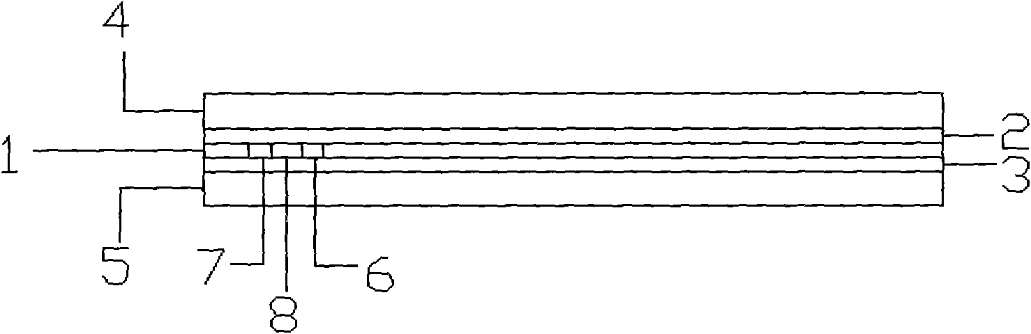
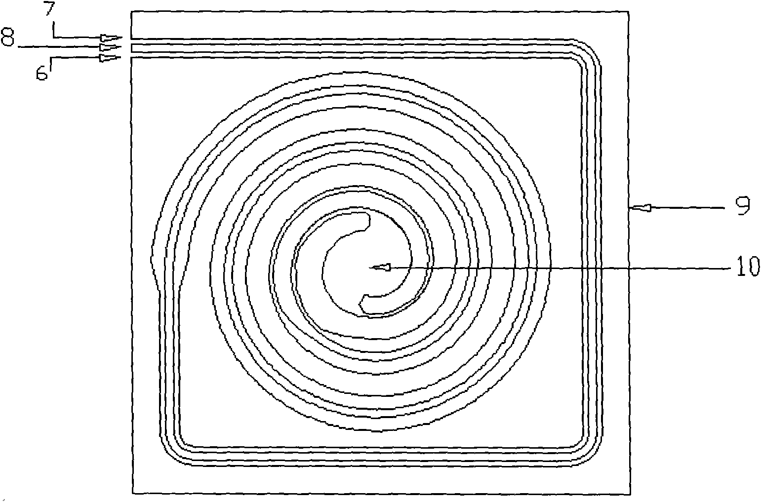
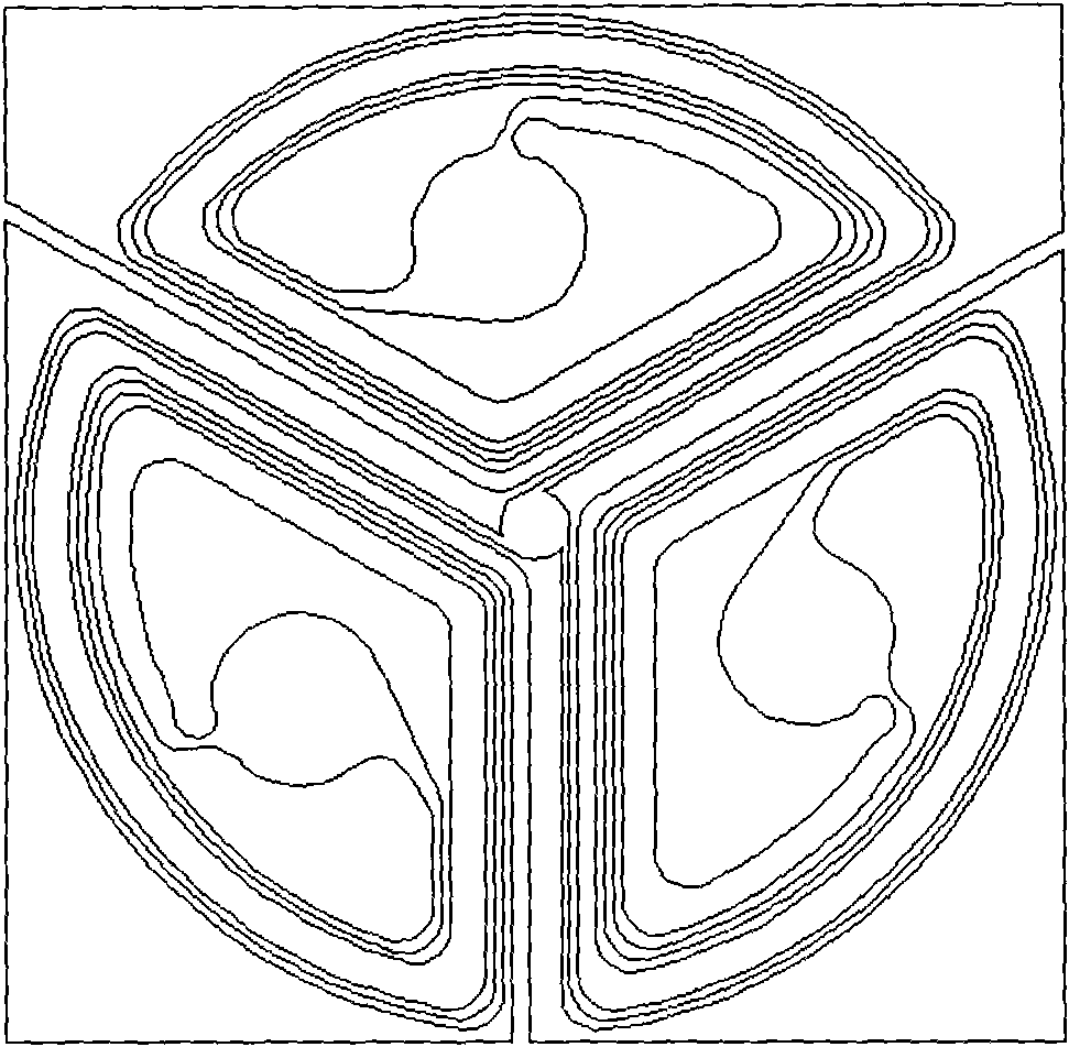
[0027] Referring to the accompanying drawings, the present invention includes an upper thermoelectric generation sheet 4 and a lower thermoelectric generation sheet 5 at the power output end, and a burner 1 with a different pipeline structure, which is usually etched from a high-temperature-resistant and non-conductive silicon wafer or silicon dioxide. Its spiral channel spirals in a circular or square shape or in any suitable shape on the same plane. In the illustrated example, the spiral groove is a square spiral, and its height and width are between 500um and 1mm. For single chamber burners ( figure 2 ), a through hole is provided at the upper thermoelectric generation sheet 4 and the lower thermoelectric generation sheet 5, and at the center position of the upper heat insulation sheet 2 and the lower heat insulation sheet 3, and the electronic ignition device is connected, so that the central through hole of the thermoelectric generation sheet is usually The diameter is ...


PUM


Abstract

The invention relates to a mini combustion-type semiconductor thermo-electric generator, which belongs to the field of electronic devices. The thermo-electric generator orderly comprises an upper thermo-electric generating sheet (4), an upper thermal-isolating baffle (2), a combustor (1), a lower thermal-isolating baffle (3) and a lower thermo-electric generating sheet (5) from top to bottom, wherein the combustor (1) comprises a substrate (9), the substrate (9) is orderly provided with a gas inlet channel (7), a combustion chamber (10) and a gas outlet channel (6), and the gas inlet channel (7) and the gas outlet channel (6) are in a parallel structure; and the diameters of the gas inlet channel (7) and the gas outlet channel (6) vary. The invention aims at the field of personal combat cells, has the advantages of small size, light weight and high continuous operation performance, and is especially suitable to provide power for mini devices in the aspects of field, military affairs and aviation with no common power sources in the field of high technology.

Description

technical field [0001] The invention relates to a micro-combustion type semiconductor thermoelectric generator with a power requirement of several watts. Background technique [0002] Batteries are indispensable equipment for the modern army. From communication instruments to reconnaissance equipment, from thermal imaging cameras to individual night vision goggles, from warship fighters to small GPS receivers, batteries are inseparable. According to statistics, a combat battalion of the US military must carry tens of thousands of batteries when it is put into battle. For a foot soldier who needs to carry 100 pounds in combat, the battery is a heavy burden. In addition to weight, battery performance is also a problem. The limited working time of traditional batteries is a common problem. [0003] The development of individual portable power supply is one of the key points in the field of electric energy. The purpose of this program is to reduce the burden on soldiers, prov...

Claims


Application Information

Patent Timeline
Patent Type & Authority Applications(China)
IPC IPC(8): H02N11/00
Inventor 韩东毛靖单华伟周文生梁林白忠恺叶莉姚君磊顾昂
Owner NANJING UNIV OF AERONAUTICS & ASTRONAUTICS
Why Eureka
Try Eureka