Capacitor voltage transformer (CVT) medium loss test method based on resonance feature

A voltage transformer, dielectric loss technology, applied in dielectric performance measurement, measurement of resistance/reactance/impedance, instruments, etc., can solve the problems of low dielectric loss value and capacitance accuracy, and achieve the ability to resist on-site power frequency interference Strong, good voltage waveform, the effect of suppressing other harmonics

Active Publication Date: 2016-12-21
汪锐
View PDF6 Cites 14 Cited by
  • Summary
  • Abstract
  • Description
  • Claims
  • Application Information

AI Technical Summary

Problems solved by technology

[0006] What the present invention is to solve is the problem of low accuracy of the dielectric loss

Method used


Image

  • Capacitor voltage transformer (CVT) medium loss test method based on resonance feature
  • Capacitor voltage transformer (CVT) medium loss test method based on resonance feature
  • Capacitor voltage transformer (CVT) medium loss test method based on resonance feature

Examples


Embodiment

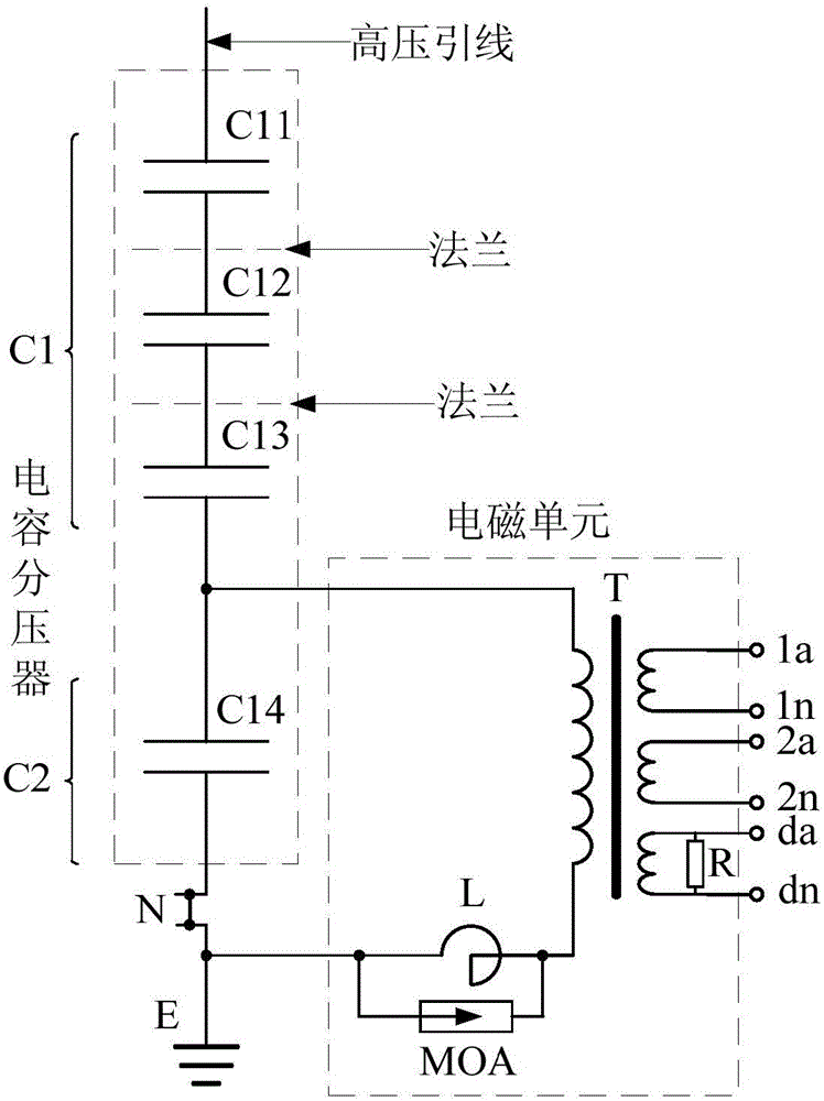
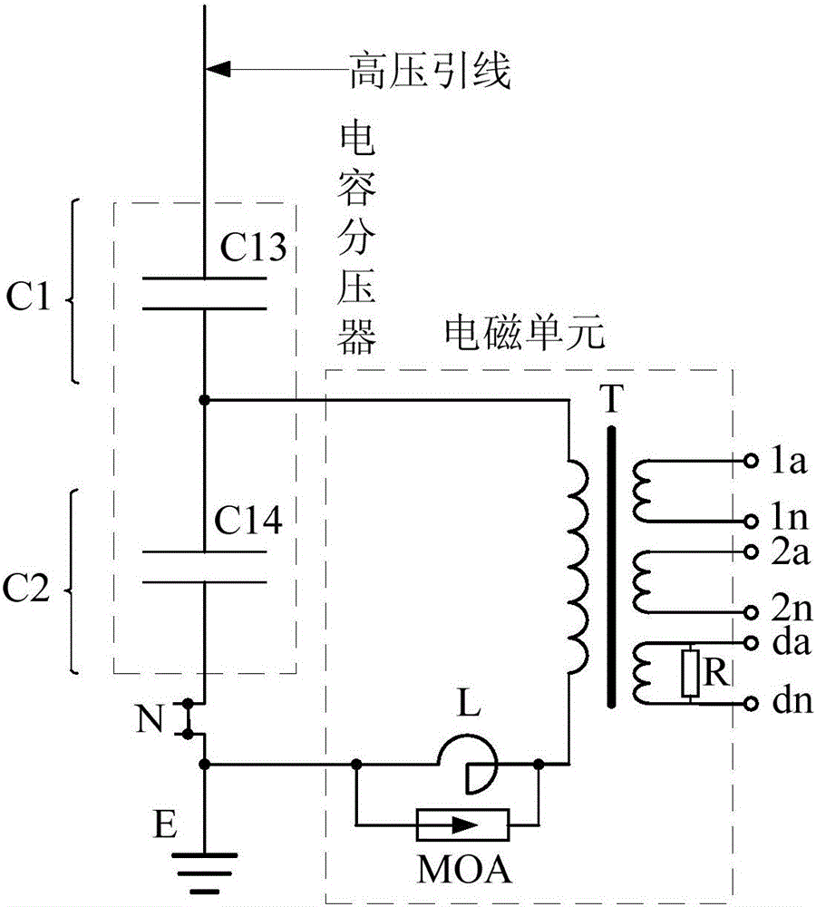
[0033] An embodiment of the present invention provides a method for testing the dielectric loss of a capacitor voltage transformer based on resonance characteristics, which is used for testing the dielectric loss of the capacitor at the bottom of the capacitor voltage transformer. This method works for figure 1 Capacitive voltage transformers with a voltage level above 110kV are also applicable to figure 2 Capacitive voltage transformers of the 110kV voltage class shown. and figure 1 Compared with the above 110kV capacitive voltage transformer shown, the difference between the 110kV voltage level capacitive voltage transformer is that the capacitive voltage divider has only one capacitor. This section of capacitor is bounded by the high-voltage lead-out line on the primary side of the intermediate transformer T. The capacitor unit C13 forms the high-voltage capacitor C1, and the capacitor unit C14 forms the medium-voltage capacitor C2. The capacitor unit C13 and the capacit...


PUM


Abstract

The invention discloses a capacitor voltage transformer (CVT) medium loss test method based on a resonance feature. The method comprises the following steps: establishing a resonance circuit model of a CVT; maintaining total currents of a circuit unchanged, and obtaining an active power increment and a reactive power increment of the resonance circuit model at a resonance state and disresonance state; and according to tg delta1=tg delta2=delta P/delta Q, obtaining medium loss of a high-voltage capacitor packaged with an intermediate-voltage capacitor and medium loss of the intermediate-voltage capacitor, wherein tg delta 1 is the medium loss of the high-voltage capacitor packaged with the intermediate-voltage capacitor, and tg delta 2 is the medium loss of the intermediate-voltage capacitor, delta P is the active power increment of the resonance circuit model at the resonance state and the disresonance state, and delta Q is the reactive power increment of the resonance circuit model at the resonance state and the disresonance state. According to the invention, by use of the resonance feature of a CVT circuit structure, an established CVT medium loss test model based on the resonance feature is more accurate compared to a conventional normal polarity method, reverse polarity method and self-excitation method test model.

Description

technical field [0001] The invention relates to the technical field of dielectric loss testing, in particular to a method for testing dielectric loss of a capacitive voltage transformer based on resonance characteristics. Background technique [0002] figure 1 It is a structural schematic diagram of a capacitor voltage transformer (CVT, Capacitor Voltage Transformers) with a voltage level above 110kV, and the capacitor voltage transformer includes a capacitor voltage divider and an electromagnetic unit. The capacitive voltage divider usually includes a plurality of capacitor units connected in series, figure 1 The shown capacitive voltage divider includes four capacitor units connected in series, that is, capacitor unit C11, capacitor unit C12, capacitor unit C13 and capacitor unit C14 in series, with the primary side high-voltage lead-out line of the intermediate transformer T as the boundary, capacitor unit C11, The capacitor unit C12 and the capacitor unit C13 form a hi...

Claims


Application Information

Patent Timeline
IPC IPC(8): G01R27/26
CPCG01R27/2694
Inventor 汪锐
Owner 汪锐
Why Eureka
Try Eureka