
State indicating circuit for computer serial interface

A technology of serial interface and status indication, applied in computing, electrical digital data processing, instruments, etc., can solve the problem of no indication of the working status of the computer serial interface

Inactive Publication Date: 2016-12-21
柳州鹏达科技有限责任公司
View PDF5 Cites 0 Cited by
  • Summary
  • Abstract
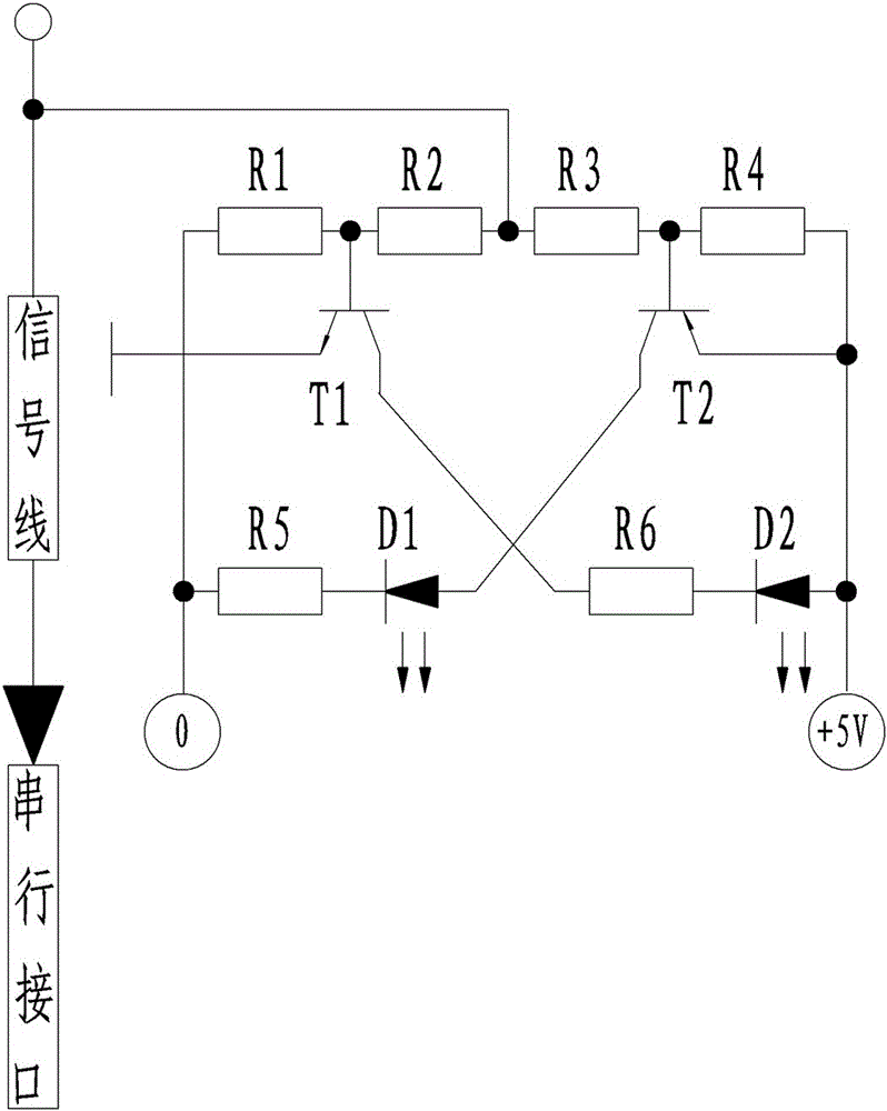
  • Description
  • Claims
  • Application Information

AI Technical Summary

Problems solved by technology

[0003] The purpose of the present invention is to provide a computer serial interface state indication circuit, which can solve the problem that the computer serial interface has no indication of the working state

Method used


Image

  • State indicating circuit for computer serial interface

Examples


Embodiment Construction

[0007] Below in conjunction with accompanying drawing and embodiment the present invention is described in further detail:

[0008] figure 1 The computer serial interface state indication circuit shown includes a first resistor R1, and the first resistor R1, the second resistor R2, the third resistor R3 and the fourth resistor R4 are connected in series, and between the first resistor R1 and the second resistor R2 The connection line of the first triode T1 is connected to the base of the first triode T1, the collector of the first triode T1 is connected to one end of the sixth resistor R6, the emitter of the first triode T1 is connected to the ground terminal, and the sixth resistor R6 The other end is connected to the cathode of the second light-emitting diode D2, the anode of the second light-emitting diode D2 is connected to the positive pole of the power supply, and the connection line between the third resistor R3 and the fourth resistor R4 is connected to the base of the...


PUM


Abstract

The invention discloses a state indicating circuit for a computer serial interface, and relates to the technical field of computer equipment manufacturing. A first resistor, a second resistor, a third resistor and a fourth resistor are connected in series; a connecting wire between the first resistor and the second resistor is connected with a base electrode of a first triode; a collector electrode of the first triode, a six resistor and a second light-emitting diode are connected in series; an emitter electrode of the first triode is connected with a grounding terminal; a connecting wire between the third resistor and the fourth resistor is connected with a base electrode of a second triode; a collector electrode of the second triode, a first light-emitting diode and a fifth resistor are connected in series; an emitter electrode of the second triode is connected with an anode of a power supply; and a connecting wire between the second resistor and the third resistor is connected with a signal line connected with the serial interface. The state indicating circuit for the computer serial interface, which is disclosed by the invention, can solve the problem that a working state of the computer serial interface is not indicated.

Description

technical field [0001] The invention relates to the technical field of computer equipment manufacturing, in particular to an indicating circuit for the working state of a computer serial interface. Background technique [0002] Computers are becoming more and more popular in today's society, but there is no indication of the working status of the computer's serial interface. Contents of the invention [0003] The purpose of the present invention is to provide a computer serial interface state indication circuit, which can solve the problem that the computer serial interface has no indication of the working state. [0004] In order to solve the above problems, the technical solution adopted by the present invention is: the computer serial interface state indication circuit includes a first resistor, and the first resistor, the second resistor, the third resistor and the fourth resistor are connected in series, and the The connecting line between the first resistor and the ...

Claims


Application Information

Patent Timeline
IPC IPC(8): G06F11/32
CPCG06F11/325
Inventor 龚湘潮
Owner 柳州鹏达科技有限责任公司
Learn More