Large-current USB Type C type socket and manufacturing method thereof

A high-current and socket technology, which is applied in the manufacture of contacts, circuits, electrical components, etc., can solve problems such as difficult high-current passage, short-circuiting of metal plates, etc., and achieve the effect of enhancing current passage and reducing impedance

Active Publication Date: 2016-12-21
SHENZHEN EVERWIN PRECISION TECH
View PDF8 Cites 16 Cited by
  • Summary
  • Abstract
  • Description
  • Claims
  • Application Information

AI Technical Summary

Problems solved by technology

[0003] The upper and lower two groups of conductive terminals respectively include a pair of ground terminals located on the outermost side and a pair of power terminals located in the middle. At present, in the case of realizing fast charging, the ground terminals and power terminals are required to

Method used


Image

  • Large-current USB Type C type socket and manufacturing method thereof
  • Large-current USB Type C type socket and manufacturing method thereof
  • Large-current USB Type C type socket and manufacturing method thereof

Examples


Embodiment 1

[0045] The following will combine Figure 1-Figure 15 The technical solution and technical principle of Embodiment 1 of the present application are introduced in detail.

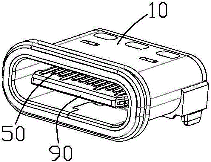
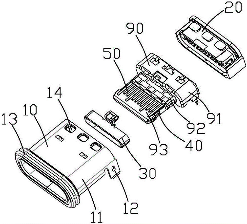
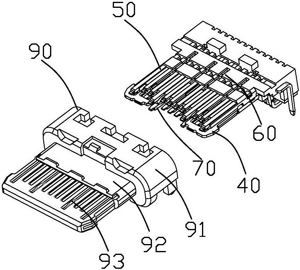
[0046] see Figure 1 to Figure 4 As shown, the high-current USB Type C socket of the present application includes a metal middle plate 40, a first terminal group 50 located on the upper and lower sides of the metal middle plate 40, a second terminal group 70, and the first terminal group 50 and the second terminal group 70. The metal middle plate 40 is formed on the integral first insulator 60, and the second insulator 80 formed on the second terminal group 70 (such as Figure 12 shown), the third insulator 90 formed by forming the first insulator 60 and the second insulator 80 as a whole, the grounding member 30 sleeved on the third insulator 90, and the third insulator 90 surrounding the third The metal shell 10 outside the insulator 90 and the fourth insulator 20 integrally formed at the rear end of the...

Embodiment 2

[0069] see Figure 16 , Figure 17 Compared with the first embodiment, the second embodiment of the present application shown is different from the second embodiment in that: the strip-shaped hole 42 on the metal middle plate 40 is penetrated in the insertion direction, so that the metal middle plate The 40-fold division is divided into a completely independent middle body part 41b and two side body parts 41a. At this time, the front ends of the first and second power terminals 50b, 70b do not need to be provided with groove structures, and there is no risk that the first and second power terminals 50b, 70b are too close to the metal middle plate 40 .

[0070] But at this time, what needs to be changed is that during the stamping process of the metal middle plate 40, the middle body part 41b and the two side body parts 41a are separately connected to the front strip of the metal middle plate 40 48 can solve the problem of strip connection caused by the separation of the mid...

Embodiment 3

[0072] see Figure 18 to Figure 20 Compared with the first embodiment, the third embodiment of the present application shown is different from the third embodiment in that: the front connecting portion 44 of the strip hole 42 of the metal middle plate 40 is cut off, and only the rear connecting portion 43 is reserved. And the rear end connecting portion 43 does not need to be thinned to form a concave portion.

[0073] The first power terminal 50b is bent upwards at the rear connecting portion 43 and then extends in parallel. The first power terminal 50b is located in front of the rear connecting portion 43 to form an upward fold A bent portion 57 and a parallel extending portion 58 extending from the upward bent portion 57 . The upwardly bent portion 57 and the parallel extending portion 58 are located on the holding portion 52 . Thus, the distance between the parallel extending portion 58 and the rear connecting portion 43 will be increased, and the upper part of the holdi...


PUM

PropertyMeasurementUnit
Thicknessaaaaaaaaaa
Thicknessaaaaaaaaaa
Thicknessaaaaaaaaaa

Abstract

Provided is a large-current USB Type C type socket, which comprises a metal middle plate provided with a main body portion; a first terminal group and a second terminal group, which are symmetrically arranged at the upper and lower sides of the metal middle plate; and an insulation body for enabling the first and second terminal groups to be integrated with the metal middle plate. The first terminal group comprises two outermost first grounding terminals, a plurality of first signal terminals, which are arranged between the two first grounding terminals, and two first power terminals; and a second terminal group comprises two outermost second grounding terminals, a plurality of second signal terminals, which are arranged between the two second grounding terminals, and two second power terminals. The thickness of the first power terminal and the thickness of the second power terminal are larger than the thickness of the first signal terminal and the thickness of the second signal terminal respectively; the main body portion of the metal middle plate is provided with strip holes in the positions corresponding to the first power terminals and the second power terminals respectively. The large-current USB Type C type socket can effectively support large-current charging.

Description

technical field [0001] The present application relates to an input and output electrical connector, especially a high-current USB Type C socket and a manufacturing method thereof. Background technique [0002] The USB3.1 Type C interface is a new interface standard launched by the USB-IF Association in 2014. This standard takes into account both size and performance, and is suitable for applications on smart terminals, but it is not backward compatible. It generally includes a metal middle plate, two sets of conductive terminals arranged on the upper and lower sides of the metal middle plate, and an insulating material that holds the metal middle plate and the conductive terminals as a whole. The metal middle plate is used to shield the high-frequency interference of the upper and lower two sets of conductive terminals, limited by the size, the distance between the two sets of conductive terminals and the metal middle plate is very small, and the terminal thickness is 0.12mm...

Claims


Application Information

Patent Timeline
IPC IPC(8): H01R13/02H01R13/6585H01R43/16H01R43/24H01R43/20
CPCH01R13/02H01R13/6585H01R43/16H01R43/20H01R43/24
Inventor 张秀华胡金奎
Owner SHENZHEN EVERWIN PRECISION TECH
Why Eureka
Try Eureka