Novel cable bridge
A cable tray, a new type of technology, applied in electrical components and other directions, can solve problems such as unfavorable wire inspection and maintenance, inability to distinguish cables and wires, and achieve the effect of simple structure, convenient installation, and enhanced heat dissipation.
- Summary
- Abstract
- Description
- Claims
- Application Information
AI Technical Summary
Problems solved by technology
Method used
Image

Examples
Embodiment 1
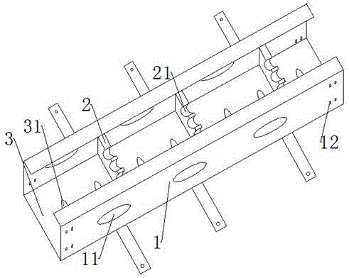
[0020] The present invention is realized through the following technical solutions: as figure 1 As shown, a new type of cable tray includes a side plate 1 and a bottom plate 3, the side plate 1 is provided with two, respectively left and right symmetrical and vertically arranged on both sides of the bottom plate 3, the side plate 1 and the bottom plate 3 are fixedly connected , the bottom plate 3 is equidistantly and parallelly arranged with a plurality of partitions 2 along the axial direction of the bottom plate 3 , and the partitions 2 are fixedly connected with the side plates 1 .
[0021] It should be noted that, through the above improvements, the partition 2 connected to the side plate 1 and the bottom plate 3 is used as a support for the cables, and the cables are placed on the partition 2. The height of the partition 2 is lower than that of the side plates 1 on both sides, that is The partition 2 is installed inside the U-shaped groove formed by the two side panels 1 ...
Embodiment 2
[0023] This embodiment is further optimized on the basis of the above embodiments, the bottom plate 3 is evenly provided with a plurality of ventilation holes B31.
[0024] It should be noted that, through the above improvements, the heat dissipation of the cable is beneficial.
[0025] Other parts of this embodiment are the same as those of the foregoing embodiments, so details are not repeated here.
Embodiment 3
[0027] This embodiment is further optimized on the basis of the above-mentioned embodiments. The partition plate 2 is perpendicular to the inner side of the side plate 1, forming an angle of 90°; the upper end of the partition plate 2 is provided with a plurality of circular grooves 21, and the The circular grooves 21 are equally spaced on the separator 2 .
[0028] It should be noted that, through the above improvements, a circular groove 21 is provided on the partition 2, and the cables are placed in the circular groove 21. When a certain cable is damaged during use, the electrician can make it more convenient. , to find out the problematic cable more quickly, to repair it in time, and to improve work efficiency; at the same time, the cables are separated, which is more conducive to the heat dissipation of the cable; the circular grooves 21 are arranged at equal intervals on the partition 2, so that the partition 2 is affected The force is more even.
[0029] Other parts of...
PUM
 Abstract
Description
Claims
Application Information