Machine tool control device and machine tool provided with the control device

A technology for a control device and a machine tool, applied in the field of machine tools, can solve the problem of not considering the vibration frequency, etc., and achieve the effects of preventing the shortening of the life, suppressing the load, and simplifying the control program

Active Publication Date: 2018-11-23
CITIZEN WATCH CO LTD
View PDF9 Cites 0 Cited by
  • Summary
  • Abstract
  • Description
  • Claims
  • Application Information

AI Technical Summary

Problems solved by technology

[0007] However, existing machine tools do not consider the above-mentioned vibration frequency, so there are cases where the above-mentioned reciprocating vibration cannot be performed under the conditions of the rotation speed of the above-mentioned relative rotation desired by the user and the number of vibrations of the cutting tool relative to the workpiece per one rotation of the workpiece. class questions

Method used


Image

  • Machine tool control device and machine tool provided with the control device
  • Machine tool control device and machine tool provided with the control device
  • Machine tool control device and machine tool provided with the control device

Examples


Embodiment 1

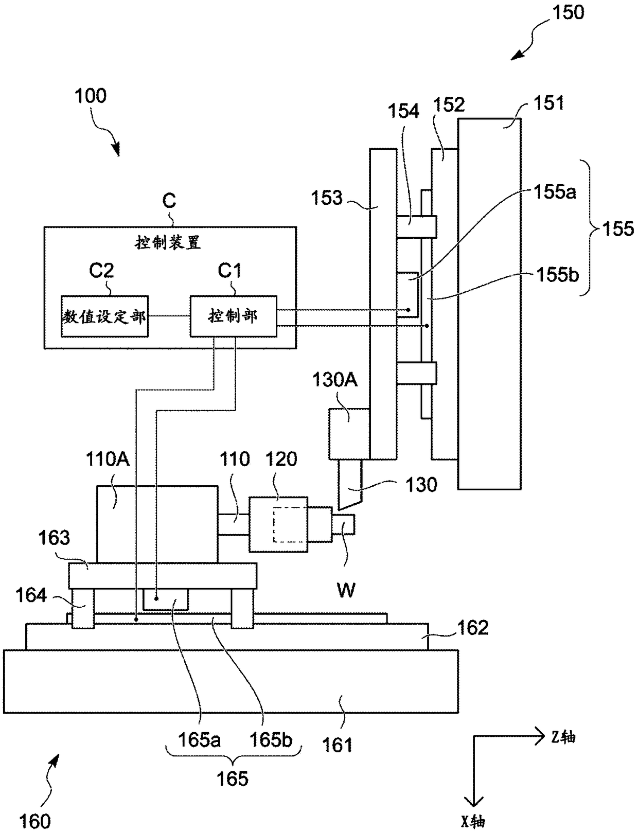
[0041] figure 1 It is a figure which shows the outline|summary of the machine tool 100 provided with the control apparatus C of 1st Example of this invention.

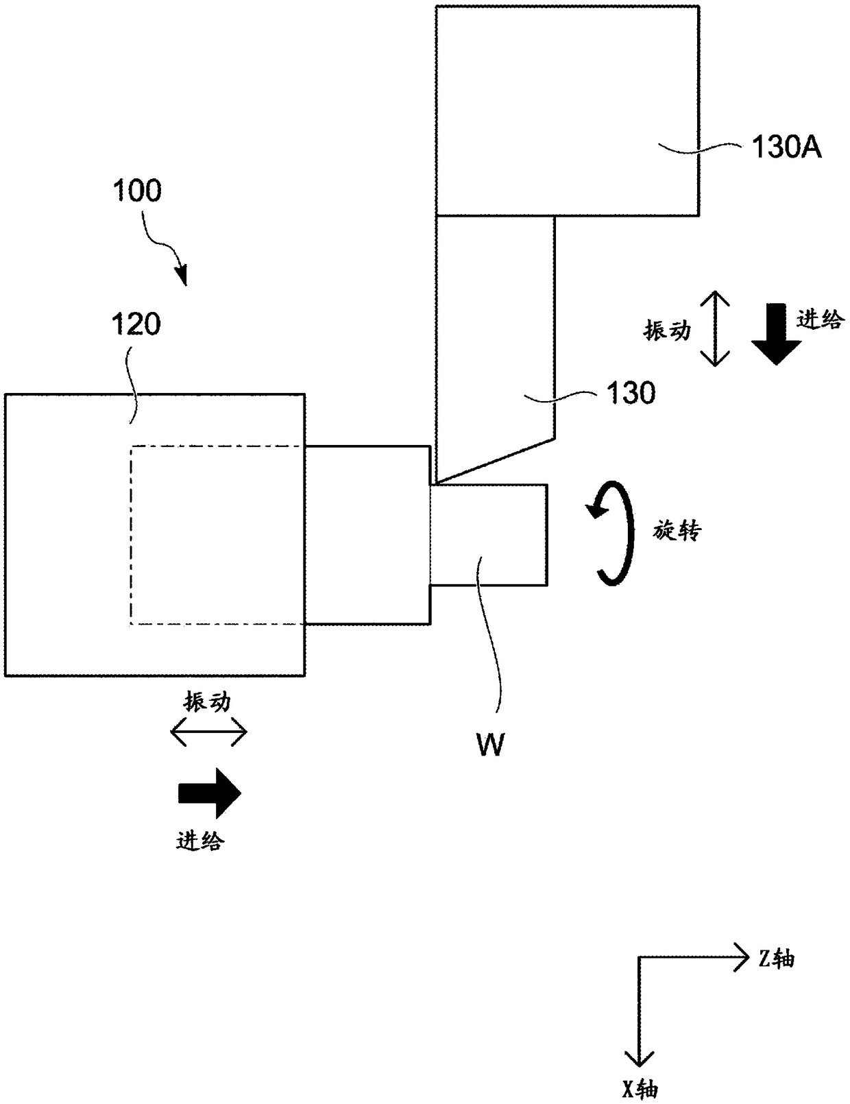
[0042] The machine tool 100 includes a spindle 110 and a cutting tool table 130A.

[0043] A chuck 120 is provided at the front end of the spindle 110 .

[0044] The workpiece W is held by the spindle 110 via the chuck 120 , and the spindle 110 constitutes a workpiece holding unit for holding the workpiece.

[0045] The spindle 110 is supported by the headstock 110A so as to be rotationally driven by the power of a spindle motor (not shown).

[0046] As the above-mentioned spindle motor, a conventionally known built-in motor or the like formed between the headstock 110A and the spindle 110 in the headstock 110A can be considered.

[0047] The headstock 110A is mounted on the bed side of the machine tool 100 so as to be movable in the Z-axis direction serving as the axial direction of the spindle 110 by the Z-axis di...

Embodiment 2

[0156] For the second embodiment, most of the elements are common to the first embodiment, so the detailed description of the common matters will be omitted, and the differences will be described below.

[0157] In the machine tool 100 of the second embodiment, the vibration number N can be fixed in advance (no need to input), the user only sets the rotation speed S, and the vibration frequency f is set according to the rotation speed S and the vibration number N, and the rotation speed S or The vibration number N is corrected.

[0158] On the other hand, in order to shorten the machining cycle, it is preferable to set the rotation of the main shaft 110 as high as possible.

[0159] For this reason, it is necessary to increase the vibration frequency f as much as possible, but it is not easy to set it too high from the viewpoint of stability control or the like.

[0160] Therefore, the rotational speed S can be increased as much as possible by reducing the vibration number N ...

Embodiment 3

[0171] For the third embodiment, most of the elements are common to the first embodiment and the second embodiment, so the detailed description of the common matters will be omitted, and the differences will be described below.

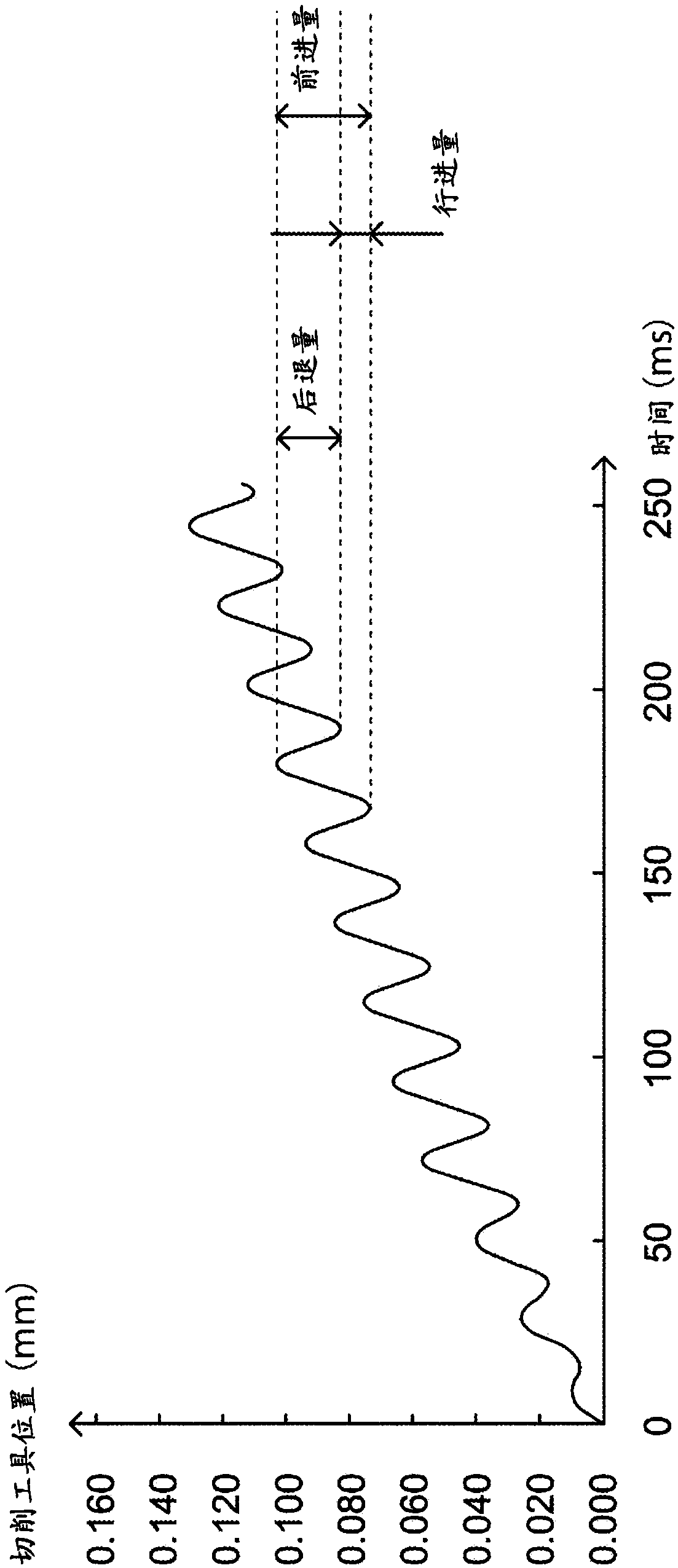
[0172] The existing machine tools described in Patent No. 5139591 and Patent No. 5139592 are configured to gradually increase the amplitude of the reciprocating vibration of the cutting tool until it reaches a predetermined value when a series (one process) of turning operations of turning the workpiece is started. Determine the specified vibration amplitude.

[0173] However, since it is not disclosed specifically how to increase, there is a problem that it is not easy to change the increase state as needed.

[0174] Therefore, the object of the invention of the third embodiment is to provide a method for simplifying the control program for gradually increasing the amplitude of the reciprocating vibration of the cutting tool until it reaches a predet...


PUM


Abstract

The present invention provides a machine tool capable of smoothly cutting a workpiece while causing a cutting tool to feed in the machining feed direction while reciprocating vibration along the machining feed direction in accordance with conditions set by the user to separate chips, and its control. device. The machine tool (100) and its control device (C) are provided with: a setting unit (C1, C2) that sets the rotational speed of the relative rotation when processing the workpiece (W), the vibration frequency of the reciprocating vibration per one revolution of the relative rotation , and based on the vibration frequency of the cycle that the control device (C) can execute the action command as a parameter, the value of the two parameters is set with respect to the control unit (C1); and the correction unit (C1), according to the set value for the two parameters The value determines the value of one parameter that has not been set as a predetermined value, and corrects the values ​​of the two parameters that have been set to predetermined values ​​based on the value determined for the one parameter that has not been set.

Description

technical field [0001] The present invention relates to a control device of a machine tool for machining a workpiece while gradually separating chips during cutting, and a machine tool provided with the control device. Background technique [0002] Conventionally, there is known a machine tool that includes: a workpiece holding unit that holds a workpiece; a tool rest that holds a cutting tool for cutting the workpiece; and a feed unit that passes the workpiece holding unit relative to the tool rest moving, causing the cutting tool to perform a feeding action relative to the workpiece in a predetermined machining feed direction; a vibration unit that vibrates the workpiece holding unit and the tool holder relative to each other, so that the cutting tool is fed along the machining directional reciprocating vibration while feeding in the machining feed direction; and a rotation unit that relatively rotates the workpiece and the cutting tool (for example, refer to Patent Docume...

Claims


Application Information

Patent Timeline
Patent Type & Authority Patents(China)
IPC IPC(8): B23Q15/013B23B1/00G05B19/4093
CPCB23Q15/0075G05B2219/49277G05B2219/49382G05B19/19G05B19/4093G05B19/182B23B25/02B23Q17/00B23B1/00
Inventor 北风绚子村松正博大山俊成三宫一彦
Owner CITIZEN WATCH CO LTD
Why Eureka
Try Eureka