Control device for machine tool, and machine tool provided with said control device

A control device and machine tool technology, applied in the field of machine tools, can solve the problem of not considering vibration frequency and the like

Active Publication Date: 2019-12-13
CITIZEN WATCH CO LTD
View PDF6 Cites 0 Cited by
  • Summary
  • Abstract
  • Description
  • Claims
  • Application Information

AI Technical Summary

Problems solved by technology

[0008] However, existing machine tools do not consider the above-mentioned vibration frequency, so there are cases where the above-mentioned reciprocating vibration cannot be performed under the conditions of the rotation speed of the above-mentioned relative rotation desired by the user and the number of vibrations of the cutting tool relative to the workpiece per one rotation of the workpiece. class questions

Method used


Image

  • Control device for machine tool, and machine tool provided with said control device
  • Control device for machine tool, and machine tool provided with said control device
  • Control device for machine tool, and machine tool provided with said control device

Examples


Embodiment 1

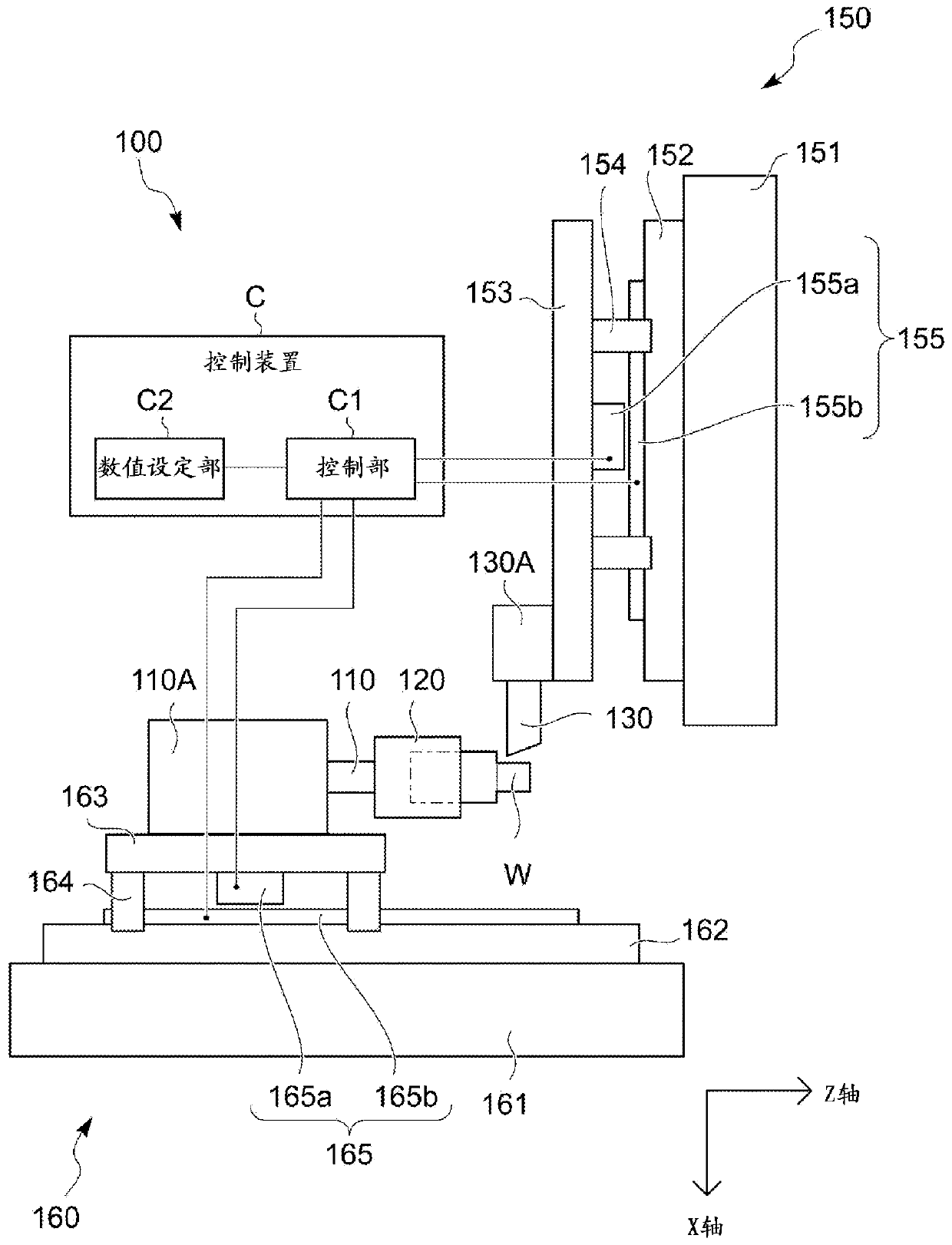
[0045] figure 1 It is a figure which shows the outline|summary of the machine tool 100 provided with the control apparatus C of 1st Example of this invention.

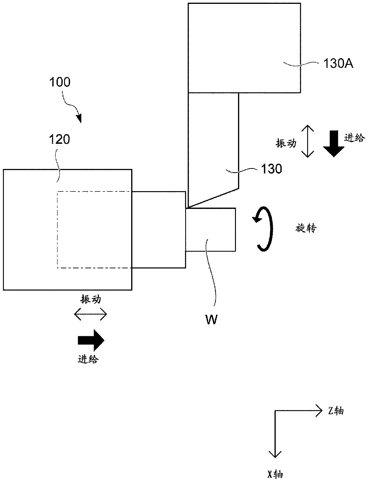
[0046] The machine tool 100 includes a spindle 110 and a cutting tool table 130A.

[0047] A chuck 120 is provided at the front end of the spindle 110 .

[0048] The workpiece W is held by the spindle 110 via the chuck 120 , and the spindle 110 constitutes a workpiece holding unit for holding the workpiece.

[0049] The spindle 110 is supported by the headstock 110A so as to be rotationally driven by the power of a spindle motor (not shown).

[0050] As the above-mentioned spindle motor, a conventionally known built-in motor or the like formed between the headstock 110A and the spindle 110 in the headstock 110A can be considered.

[0051] The headstock 110A is mounted on the bed side of the machine tool 100 so as to be movable in the Z-axis direction serving as the axial direction of the spindle 110 by the Z-axis di...

Embodiment 2

[0139] The second embodiment changes the parameters, conditions, etc. of the first embodiment. Most of the elements are common to the first embodiment. Therefore, the detailed description of the common items is omitted, and the differences are described below.

[0140] In the machine tool 100 of the second embodiment, the user sets the rotational speed S to the control unit C1 via the numerical value setting unit C2 and the like.

[0141] The setting of the rotation speed S to the control unit C1 can be performed by not only inputting the value of the rotation speed S into the control unit C1 as a parameter value, but also by writing the value of the rotation speed S in a machining program, for example.

[0142] The control unit C1 controls to rotate the main shaft 110 based on the set rotation speed S, and to move the headstock 110A or the cutting tool table 130A while vibrating back and forth so that the cutting tool 130 moves in the machining feed direction while vibrating b...

Embodiment 3

[0161] For the third embodiment, most of the elements are common to the first embodiment and the second embodiment, so the detailed description of the common matters will be omitted, and the differences will be described below.

[0162] In the machine tool 100 of the third embodiment, similar to the first embodiment or the second embodiment, if the user sets two (rotational speed S and vibration number N) or one (rotational speed S) of the three parameters to If it is set to the control unit C1, it is possible to make the cutting tool 130 move along the above-mentioned machining feed direction under the condition that is relatively close to the rotation speed S and the vibration number N expected by the user or based on the preset rotation speed S. The reciprocating vibration of the workpiece W is smoothly cut while feeding in the machining feed direction to separate the chips.

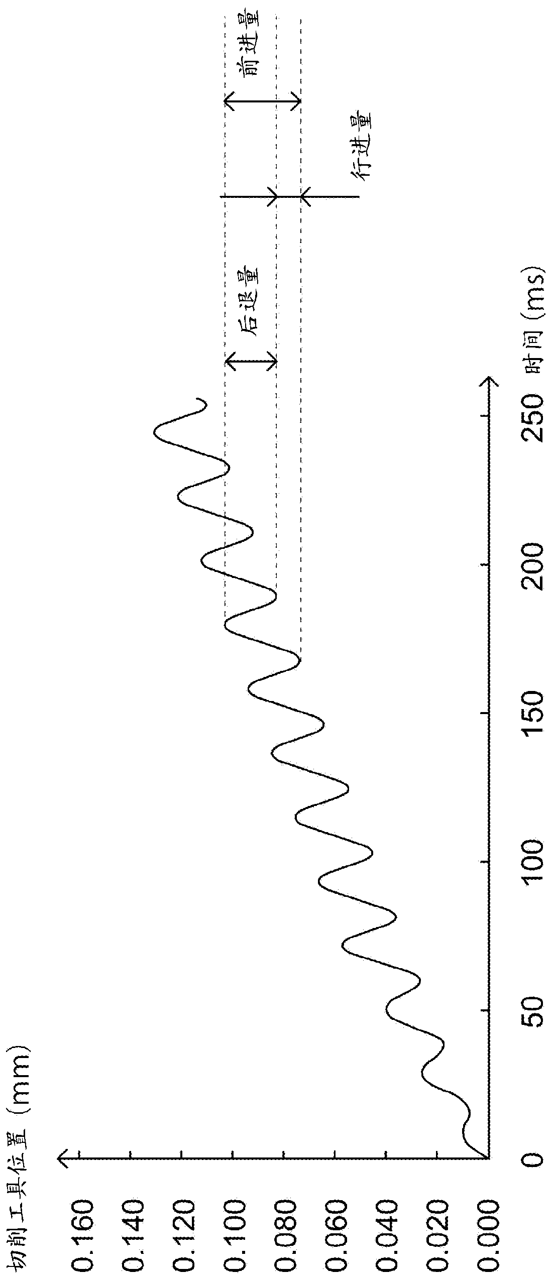
[0163] like Figure 8A shown, with Figure 4 Similarly, the main shaft rotates once and the cutt...


PUM


Abstract

The present invention provides a machine tool and a control device for the machine tool that can smoothly cut a workpiece while segmenting chips by feeding a cutting tool in a feed direction while reciprocally vibrating the cutting tool along the feed direction on the basis of a condition set by a user. The machine tool (100) or the control device (C) includes the control section (C1) that determines a number of rotations of the relative rotation and a number of vibrations of the reciprocal vibration per rotation of the relative rotation when the workpiece (W) is machined in accordance with avibration frequency dependent on a period in which an operating instruction can be executed.

Description

[0001] This application is made by the applicants "Citizen Watch Co., Ltd.", "Citizen Seiki Co., Ltd.", the title of the invention is "Control Device for Machine Tool and Machine Tool Equipped with the Control Device", and the filing date is "March 24, 2015". A divisional application of the parent application with the application number "201580016409.5". technical field [0002] The present invention relates to a control device of a machine tool for machining a workpiece while gradually separating chips during cutting, and a machine tool provided with the control device. Background technique [0003] Conventionally, there is known a machine tool that includes: a workpiece holding unit that holds a workpiece; a tool rest that holds a cutting tool for cutting the workpiece; and a feed unit that passes the workpiece holding unit relative to the tool rest moving, causing the cutting tool to perform a feeding action relative to the workpiece in a predetermined machining feed dire...

Claims


Application Information

Patent Timeline
Patent Type & Authority Applications(China)
IPC IPC(8): B23Q15/12B23Q15/013
CPCB23B1/00B23Q15/0075G05B2219/49277G05B2219/49382G05B19/19G05B19/4093B23B25/02B23C2250/16G05B19/18G05B2219/49053B23Q17/12G05B2219/49055B23Q17/10B23B29/125
Inventor 三宫一彦松本仁篠原孝哲篠原浩大山俊成今崎能吉
Owner CITIZEN WATCH CO LTD
Why Eureka
Try Eureka