end mill

A technology of end mills and peripheral cutting edges, applied in the field of end mills, which can solve the problems of workpiece material vibration, increased cutting resistance, and impossibility of cutting, and achieve smooth cutting, good discharge, and suppress the generation of burrs Effect

Inactive Publication Date: 2016-01-20
MITSUBISHI MATERIALS CORP
View PDF12 Cites 0 Cited by
  • Summary
  • Abstract
  • Description
  • Claims
  • Application Information

AI Technical Summary

Problems solved by technology

[0010] Therefore, especially in thin plate processing, there is a possibility of vibration or delamination of the workpiece material due to the force in the opposite direction.
[0011] In addition, in order to suppress the generation of burrs, for example, it is also effective to use a plurality of outer peripheral cutting edges as straight cutting edges without a helix, but in this case, the cutting resistance is significantly increased, and smooth cutting cannot be performed.
[0012] In addition, in the end mill described in Patent Document 2, it is necessary to form different helical cutting edges (peripheral cutting edges) on the front end side and the shank side. knife making is hard
That is, since it is a joint-type end mill with different cutting edges (peripheral cutting edges) on the front end side and the shank side, it cannot be produced cheaply
In addition, chips may collide at the joint part, making it difficult to ensure chip discharge
In addition, since the joining portion has a boundary portion of the cutting edge, and the boundary portion is transferred in a line shape on the finished surface, there remains a problem that a problem may arise in the properties of the finished surface.

Method used


Image

  • end mill
  • end mill
  • end mill

Examples


Embodiment Construction

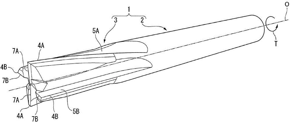
[0031] Below, use Figure 1 to Figure 5 Embodiments of the end mill according to the present invention will be described.

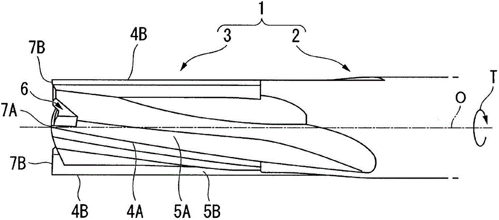
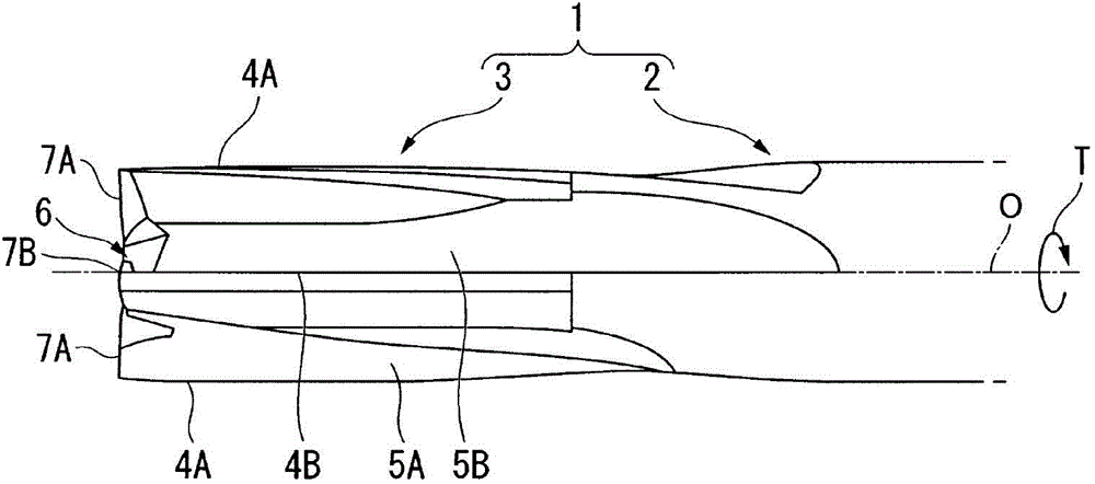
[0032] Such as figure 1 and image 3 As shown, the end mill has a substantially cylindrical end mill body 1 formed of a hard material such as cemented carbide and having an axis O as a center. In the end mill body 1, its rear end side part ( figure 2 and image 3 The right part in the middle) is the cylindrical handle part 2, and the front part ( figure 2 and image 3 The left part in ) is the cutting edge 3.

[0033] When cutting a workpiece material with an end mill, the shank portion 2 is held by the main shaft of the machine tool and rotates about the axis O in the direction T of rotation of the end mill. Then, the end mill main body 1 is sent out in a direction intersecting the axis O by the main shaft of the machine tool, and in some cases also sent out to the front end side in the axial direction, thereby cutting the workpiece material wit...


PUM


Abstract

The present invention provides an end mill capable of suppressing the generation of burrs in response to various cutting conditions and various workpiece thicknesses, and capable of smooth cutting without problems in chip discharge performance and the properties of the finished surface. Machining. In the end mill of the present invention, a first peripheral cutting edge (4A) formed in a spiral shape around the axis (O) is provided on the cutting edge portion (3) of the end mill body (1) rotating around the axis (O) and A linear second peripheral cutting edge (4B) extending parallel to the axis (O). In addition, the first peripheral cutting edge (4A) is formed in a helical shape by spiraling in the rotation direction (T) of the end mill from the rear end side toward the front end side.

Description

technical field [0001] The invention relates to an end mill with a helical cutting edge. Background technique [0002] An end mill with a helical edge improves sharpness by reducing cutting resistance, but produces structural burrs at the end of the cutting edge. In particular, when the workpiece material is a material that easily generates burrs or the shape is a plate, the problem of burrs becomes significant. In recent years, plate materials including carbon fiber composite materials (CFRP), which are difficult-to-cut materials used in aircraft, have been machined using end mills with helical cutting edges. layer (delamination), so it is necessary to avoid the occurrence of this burr. [0003] As an end mill that solves such a burr problem, for example, Patent Document 1 discloses an end mill that includes a left-helical peripheral cutting edge and a right-helical peripheral cutting edge on the outer periphery of a linearly formed shaft body. Since such an end mill inc...

Claims


Application Information

Patent Timeline
Patent Type & Authority Patents(China)
IPC IPC(8): B23C5/10
CPCB23C5/10B23C2210/0492B23C2226/27Y10T407/1948
Inventor 畔上贵行
Owner MITSUBISHI MATERIALS CORP
Why Eureka
Try Eureka