Power module

A power module and component technology, applied in the direction of electric components, transmission boxes, transmission parts, etc., can solve the problems of unfavorable use of small-volume robot machinery and equipment, large volume, and many parts

Active Publication Date: 2016-12-28
深圳市极拓医疗科技有限公司
View PDF11 Cites 11 Cited by
  • Summary
  • Abstract
  • Description
  • Claims
  • Application Information

AI Technical Summary

Problems solved by technology

[0003] However, the power modules in the prior art are usually composed of motors, couplings, reducers, controllers and other components, and the motors and reducers are usually connected externally. To achieve a large reduction ratio and hi

Method used


Image

  • Power module
  • Power module
  • Power module

Examples


no. 1 example

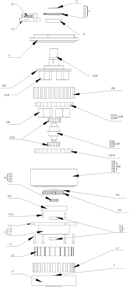
[0050] see figure 1 , the power module of this embodiment includes a motor 1, a planetary reduction mechanism 2A, a cycloidal reduction mechanism 2B and a motor output mechanism. In this embodiment, the motor 1 includes a stator assembly 11 and a motor outer rotor 13, and the motor outer rotor 13 is designed as Cylindrical hollow body structure, inside accommodates the stator assembly 11 embedded in the planetary reduction mechanism 2, the motor output shaft 3 is the motor output mechanism of this embodiment, and the motor output shaft 3 is located at the center of the stator assembly 11 and the motor outer rotor 13 position, and the motor output shaft 3 is the main rotational speed transmission mechanism of the entire motor 1 and the planetary reduction mechanism 2A.

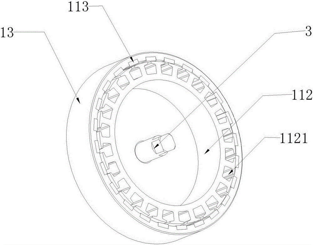
[0051] see further figure 2, in this embodiment, the stator assembly 11 includes a stator fixing flange 111, a stator iron core 112 and a magnetic steel 113, and the stator fixing flange 111 is also a cylindr...

no. 2 example

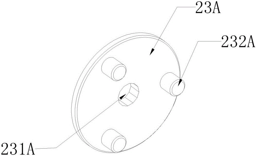
[0064] The above is a structure designed to use the planetary reduction mechanism 2A and the cycloidal reduction mechanism 2B together when a large reduction ratio is required. According to the actual field where the power module is used, the planetary reduction mechanism 2A can also be used alone. The specific connection The way is to accommodate the planetary reduction mechanism 2A in the stator assembly 11 of the motor 1. In this embodiment, the structure of the motor 1 is the same as that of the first embodiment, and the main structure of the planetary reduction mechanism 2A is also the same as that of the first embodiment. same, except that Figure 8 As shown, the structure of the planetary carrier 23A' of the planetary reduction mechanism 2A in this embodiment is different, wherein the structure of the fixed protrusion 232A' remains unchanged, but the central part of the planetary carrier 23A' is not provided with an output through hole structure, and It is a planetary o...

no. 3 example

[0066] In the case of a small reduction ratio requirement, a situation in which only the cycloidal reduction mechanism 2B is used is also designed. The specific connection method is: the stator fixing flange 111 is not limited to the design of a groove structure, and when no groove is designed In terms of structure, the connection structure of the entire cycloidal reduction mechanism 2B is the same as that of the first embodiment, the stator fixing flange 111 and the pin gear housing 21B are fixed by the fixing pin 14, and the motor output shaft 3 and the eccentric shaft 221B are connected by a coupling (not shown in the figure) Just connect, and other components remain unchanged. If the stator fixing flange 111 is designed with a groove structure, the inner wall of the groove can be designed as a concave-convex structure on the inner wall of the pin gear housing 21B, and the pin teeth 25B are accommodated in the stator fixing flange 111, and the pin gear housing 21B is directl...


PUM


Abstract

The invention discloses a power module. The power module comprises a motor serving as a power source of the power module, a reducing mechanism used for matching rotational speed and transmitting torque and a motor output mechanism for rotational speed transmission. A stator module of the motor is provided with a hollow groove, the reducing mechanism is contained in the hollow groove, and the motor output mechanism is connected with the motor and the reducing mechanism at the same time. According to the power module, the reducing mechanism is arranged in the stator module of the motor; compared with the mode that in the prior art, a reducing mechanism is externally connected with a motor, the concept is unique, the size of the whole power module is greatly reduced, and the power module is more suitable for being arranged in a small machine; a one-level reducing mechanism or a multi-level reducing mechanism can be selected to be used as the reducing mechanism according to the demand of the whole power module, all the components are relatively independent and complementary, and the power module is flexible and changeable in use.

Description

technical field [0001] The invention relates to the field of power drive technology, in particular to a small-volume power module. Background technique [0002] A robot is a machine device that performs work automatically. It can accept human command, run pre-programmed programs, and act according to principles formulated with artificial intelligence technology. Its mission is to assist or replace work performed by humans, such as manufacturing, construction, or hazardous work. With the development of technology, robots are often used in many production lines or daily services, and the current robots are manufactured towards imitating humans, or manufactured into small-sized robots that perform a variety of complex actions. Performance parameters such as module accuracy and reduction ratio must be improved. [0003] However, the power modules in the prior art are usually composed of motors, couplings, reducers, controllers and other components, and the motors and reducers...

Claims


Application Information

Patent Timeline
IPC IPC(8): F16H57/02B25J9/12H02K7/10H02K7/116
CPCB25J9/102B25J9/12F16H57/02F16H2057/02026F16H2057/02039F16H2057/02086H02K7/10H02K7/116
Inventor 梁哲石枝春李长城段璞
Owner 深圳市极拓医疗科技有限公司
Why Eureka
Try Eureka