Refrigerator and method of supplying water in refrigerator
A technology for a refrigerator and a water supply pipe is applied in the field of refrigerators and water supply in refrigerators, and can solve the problems of uneven distribution of water and inability of water to move.
Inactive Publication Date: 2016-12-28
DONGBU DAEWOO ELECTRONCIS CORP
7 Cites 2 Cited by
AI-Extracted Technical Summary
Problems solved by technology
Therefore, water cannot move smoothly through the water supply groove of the ice tray
Thi...
Method used
[0044] A heater 213 for preventing the feeder 211 and the water supply pipe 212 from freezing and breaking can be provided in the feeder pipe 211 and the workpiece in such a manner as to surround the outer circumference of the feeder 211 and the water supply pipe 212. In addition, a waterproof film 214 is provided outside the heater 213 in such a manner as to surround the outer circumference of the feeder 211 and the water supply pipe 212 . This makes it possible to isolate the heater 213 from moisture, thereby preventing accidents such as short circu...
Abstract
According to an embodiment, a refrigerator, comprising: a main body comprising a food storage space; a door installed in the main body and configured to open and close the food storage space; and an ice-making device installed in the food storage space, wherein the ice-making device comprises a case comprising a cooling space defined therein, a cooling unit configured to cool the cooling space, and an ice-making system disposed in the cooling space and configured to produce ice pieces, the ice-making system comprising an ice tray comprising a plurality of ice-making spaces capable of retaining water, and a water supply unit configured to supply water to the ice-making spaces, the water supply unit comprises a feeder pipe configured to feed water to the ice-making system, and a water supply pipe connected to the feeder pipe and disposed above the ice tray to extend along a length direction of the ice tray, and a plurality of water supply holes is formed in the water supply pipe in the positions corresponding to the ice-making spaces so that water is supplied to the respective ice-making spaces through the respective water supply holes.
Application Domain
Mechanical apparatusIce production +3
Technology Topic
Cooling UnitsEngineering +3
Image
Examples
- Experimental program(1)
Example Embodiment
[0029] In the following detailed description, reference is made to the accompanying drawings, which form a part of this application document. The illustrative embodiments described in the detailed description, drawings, and claims are not intended to be limiting. Other embodiments may be utilized, and other changes may be made, without departing from the spirit and scope of the subject matter presented herein.
[0030] One or more exemplary embodiments of the present disclosure will be described more fully hereinafter with reference to the accompanying drawings, wherein one or more exemplary embodiments of the present disclosure can be easily ascertained by those skilled in the art. As those skilled in the art would realize, the described exemplary embodiments may be modified in various different ways, all without departing from the spirit or scope of the present disclosure, which is not limited to the exemplary implementations described herein. example.
[0031] Note that the figures are schematic and not necessarily to scale. Relative sizes and ratios of components in the drawings may be enlarged or reduced in size thereof, and predetermined sizes are only exemplary and not restrictive. The same reference numerals designate the same structure, element or part shown in two or more drawings, so as to show similar characteristics.
[0032] The exemplary embodiments of the present disclosure illustrate idealized exemplary embodiments of the present disclosure in more detail. Therefore, various modifications of the drawings are expected. Accordingly, exemplary embodiments are not limited to the particular forms of regions illustrated, and include modifications of forms by, for example, manufacturing.
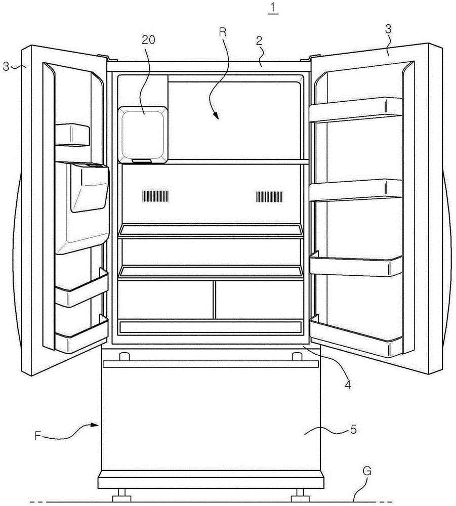
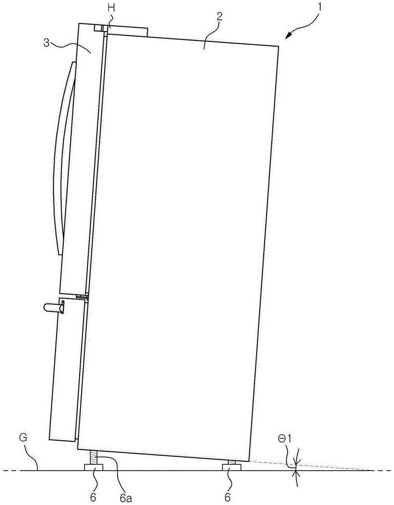
[0033] figure 2 is a front view of a refrigerator according to an aspect of the present disclosure. image 3 is shown in figure 2 A side view of the refrigerator shown in , installed at an angle with respect to the floor surface, with the door of the refrigerator kept closed.
[0034] refer to figure 2 and image 3 , the refrigerator 1 according to the present embodiment may include: a main body 2 including a casing; a barrier 4 for dividing the food storage space formed inside the main body 2 into an upper refrigerating compartment R and a lower freezing compartment F; A refrigerating compartment door 3 provided at opposite edges of the front surface of the main body 2 and configured to selectively close the refrigerating compartment R by its rotation; and a freezing compartment door 5 configured to close the freezing compartment F front opening. In the present embodiment, an example is illustrated in which an ice making device 20 is provided in one side region of the upper part of the refrigerating compartment R. As shown in FIG. However, this is only an example. The ice maker 20 can be located elsewhere in the refrigerated compartment R or in one of the refrigerated compartment doors 3 .
[0035] The main body 2 may be mounted on the ground surface G by means of adjustable feet 6 capable of supporting the main body 2 at a position between the ground surface G and the main body 2 . Each of the adjustable feet 6 may include a height adjustment screw 6a whose length coupled with the bottom surface of the main body 2 is adjustable. The height of the main body 2 from the ground surface G can be adjusted by tightening or loosening the height adjusting screw 6a. like image 3 As illustrated in , the main body 2 can be lifted by the adjustable feet 6 so that the front end of the main body 2 is positioned higher than the rear end thereof. As a result, the main body 2 is inclined downward at a predetermined angle θ1 from the front end portion of the main body 2 toward the rear end portion thereof. In this case, even if the user does not push the refrigerating compartment door 3 after opening the refrigerating compartment door 3, the refrigerating compartment door 3 rotates back around the hinge H to automatically close. This enables the user to use the refrigerator conveniently.
[0036] Figure 4 Yes figure 2 An exploded perspective view of the ice maker provided in the refrigerator shown in , while Figure 5 Yes Figure 4 Side sectional view of the ice maker shown in .
[0037] refer to Figure 4 and Figure 5 , the ice making device 20 of the refrigerator according to this embodiment is installed in the storage space of the refrigerator 1 and can evenly supply water to the ice making space 13 of the ice tray 10 (see Image 6 ). The ice making device 20 may include: a cabinet 100; a cooling unit (not shown) configured to cool the inside of the cabinet; an ice making system 200 on which the ice tray 10 is installed; an ice bucket 320 in which the ice tray 10 is stored. 10; and a feeder system 400 configured to feed ice cubes from the ice bucket 320.
[0038] A cooling space 105 in which ice cubes can be made is formed within the case 100 . The ice making system 200 may be disposed on an upper side inside the cooling space 105 .
[0039] The cooling unit is used to cool the cooling space 105 . The cooling unit can cool the ice tray 10 by generating cold air and supplying it to the ice making system 200 or bringing a cooling pipe supplied with low-temperature refrigerant into contact with the lower side of the ice tray 10 . The cooling unit may include a compressor, a condenser, an expansion valve, and an evaporator to form a cooling cycle. Cool air may be supplied to the ice tray 10 through the discharge duct 310 and the cool air guide unit 220 by a blower or the like.
[0040] In this embodiment, an example in which cool air is supplied to the cooling space 105 will be described.
[0041] The ice making system 200 may include: an ice tray 10; a water supply unit 210 configured to supply water to the ice tray 10; a cool air guide unit 220 configured to guide a flow of cool air so that the cool air supplied from the cooling unit air moves along the lower surface of the ice tray 10 ; and the rotation unit 230 configured to drop ice cubes made in the ice tray 10 into the ice bucket 320 located under the ice tray 10 .
[0042] Image 6 is a diagram illustrating a structure through which water is supplied to Figure 5 the ice tray of the ice maker shown in .
[0043] refer to Image 6 , the water supply unit 210 is configured to supply water to the ice tray 10 . The water supply unit 210 may include: a feeder pipe 211 connected to a water supply tank, a tap water line, etc. and configured to supply water to the ice making system 200; and a water supply pipe 212 connected to the feeder pipe 211 and arranged in the ice tray 10. above to extend along the length direction of the ice tray 10 . A plurality of water supply holes 215 are formed at positions of the water supply pipe 212 corresponding to the ice making space 13 so that water can be supplied to the ice making space 13 through the water supply holes 215 .
[0044] A heater 213 for preventing the feeder 211 and the water supply pipe 212 from freezing and breaking can be provided in the feeder pipe 211 and the workpiece in such a manner as to surround the outer circumference of the feeder 211 and the water supply pipe 212 . In addition, a waterproof film 214 is provided outside the heater 213 in such a manner as to surround the outer circumference of the feeder 211 and the water supply pipe 212 . This makes it possible to isolate the heater 213 from moisture, thereby preventing accidents such as short circuits.
[0045] Also, the diameter of the water supply hole 215 may be set to be larger as the water supply hole 215 is farther away from the supplier pipe 211 . Water supplied via the supplier pipe 211 flows along the water supply pipe 212 . At this time, water is first supplied to the water supply hole 215 that is closer to the feeder pipe 211 , and is then supplied to the water supply hole 215 that is farther from the feeder pipe 211 . Therefore, if the water supply holes 215 are equal in diameter to each other, a large amount of water is supplied to the water supply holes 215 that are closer to the supplier pipe 211 . That is, the amount of water supplied to the ice making space 13 of the ice tray 10 may be uneven.
[0046] On the other hand, if the diameter of the water supply hole 215 is set to be larger as the water supply hole 215 is farther away from the supplier pipe 211, the amount of water supplied to the ice making space 13 becomes uniform in all spaces. The diameter of each of the water supply holes 215 may be set based on the volume of the ice making space 13, the amount and pressure of water supplied from the supplier 211 and the water supply pipe 212, the length of the water supply pipe 212, and the like.
[0047] The ice tray 10 may be made of a metal material (for example, aluminum) with high thermal conductivity. As the thermal conductivity of the ice tray 10 becomes higher, it becomes possible for the ice tray 10 to improve the heat exchange rate of water and cold air, so that the ice tray 10 can be used as a kind of heat exchanger. Cooling fins (not shown) for increasing a contact area of the ice tray 10 with cold air may be provided on the lower surface of the ice tray 10 .
[0048] The cool air guide unit 220 functions to guide cool air supplied from the cooling unit toward the lower side of the ice tray 10 . The cool air guide unit 220 may be connected to the exhaust duct 310 which is a path through which cool air is supplied from the cooling unit. The cool air guide unit 220 may include cool air guide films 221 and 222 connected to at least one surface of the discharge duct 310 . like Figure 5 As illustrated in , the cool air guide unit 220 may include a first cool air guide film 221 extending from an upper surface of the discharge duct 310 and a second cool air guide film 222 extending from a lower surface of the discharge duct 310 .
[0049] Cool air guided by the cool air guide films 221 and 222 can move toward the lower surface of the ice tray 10 . As the cold air exchanges heat with the ice tray 10, the water held in the ice tray 10 is phased into ice cubes.
[0050] The rotation unit 230 may include: a motor 232 ; a rotation shaft 231 connected to the ice tray 10 and rotated by the motor 232 ; and a motor housing 233 configured to receive the motor 232 therein.
[0051] The rotation unit 230 may drop the ice cubes thus prepared into the ice bucket 320 disposed under the ice tray 10 . Specifically, by virtue of the rotation of the rotation shaft 231 , the ice tray 10 may be rotated such that the upper surface of the ice tray 10 faces the ice bucket 320 . If the ice tray is rotated at a certain angle or more, the ice tray 10 is distorted by an interference film (not shown). Ice cubes located in the ice tray 10 may drop into the ice bucket 320 due to this twisting action.
[0052] Alternatively, a plurality of ejectors (not shown) may be provided along the length direction of the rotation shaft 231 . In this case, the ice tray 10 does not rotate, but ice cubes can be taken out from the ice tray 10 by the rotation of the ejector of the rotation shaft 231 .
[0053] In addition, a deicing heater 240 may be provided in the ice tray 10 such that the deicing heater 240 may heat the ice tray 10 during or before the rotation of the rotation shaft 231 . The surface of the ice cubes accommodated in the ice tray 10 is melted and separated from the ice tray 10 by the heating effect of the deicing heater 240 .
[0054] The feeder system 400 may include an auger 410 and an auger motor 420 configured to feed ice cubes to the discharge portion 600 . The auger 410 may be a rotating membrane including a screw or a spiral blade. The auger 410 is rotated by an auger motor 420 . The auger 410 is disposed within the ice bucket 320 . Ice cubes stacked in the ice bucket 320 may be inserted into grooves defined by the spiral part or the blade and may be supplied to the discharge part 600 . Auger motor 420 may be housed within auger motor housing 430 .
[0055] The discharge part 600 may be coupled to a dispenser (not shown) provided in one of the refrigerating compartment doors 3 . According to the user's selection, the ice cubes served by the dispenser system 400 may be dispensed to the user via the dispenser.
[0056] Operations and effects of a refrigerator and a method of supplying water in the refrigerator according to an aspect of the present disclosure will now be described.
[0057] In the ice making device 20 according to the present embodiment, water may be uniformly supplied to the ice making space 13 of the ice tray 10 via the water supply unit 210 . Specifically, the water supply pipe 212 extending along the length direction of the ice tray 10 is installed above the ice tray 10 including the ice making space 13 formed therein. The water supplied through the water supply pipe 212 is supplied to the ice making space 13 through the water supply holes 215 arranged along the length direction of the water supply pipe 212 .
[0058] The water supplied through the supplier pipe 211 moves along the length direction of the water supply pipe 212 and flows into the ice making space 13 under the water supply pipe 212 through the water supply hole 215 of the water supply pipe 212 . The diameter of the water supply hole 215 is larger as the water supply hole 215 is farther away from the feeder pipe 211 . Therefore, the amount of water supplied through the water supply holes 215 farther from the feeder pipe 211 within a unit time is greater than the amount of water supplied through the water supply holes 215 closer to the feeder pipe 211 within a unit time. Therefore, it is advantageous that the amount of water supplied to each ice-making space 13 becomes uniform in all the spaces.
[0059] If the water supply unit 210 completes water supply, cool air generated through the action of the compressor, condenser, expansion valve, and evaporator is supplied to the cooling space 105 through the discharge pipe 310 . The cold air thus supplied may freeze water contained in the ice tray 10 disposed within the cooling space 105 .
[0060] The cold air moves along the lower surface of the ice tray 10 and exchanges heat with the lower surface of the ice tray 10, thereby freezing water contained in the ice tray 10 into ice cubes. Since the heater 213 is provided in the supplier 211 and the water supply pipe 212, the supplier 211 and the water supply pipe 212 can be prevented from being frozen and broken due to cold air. In addition, the waterproof membrane 214 prevents the heater 213 from contacting water. Therefore, the occurrence of a short-circuit accident can be prevented.
[0061] The surface of the ice cubes made in the ice tray 10 is melted by the heating effect of the deicing heater 240 . As a result, the ice cubes are easily separated from the ice tray 10 . Thereafter, the ice cubes fall down and are stacked in the ice bucket 320 due to the rotation of the rotation shaft 231 .
[0062] In the ice making device 20 according to the present embodiment, water may be supplied to the respective ice making spaces 13 through the water supply unit 210 . Therefore, the amount of water supplied to each ice making space 13 becomes uniform in the space. Accordingly, even when the ice tray 10 is provided in the refrigerator 1 installed obliquely at a predetermined angle with respect to the ground surface G by the adjustable feet 6, the amount of water supplied to the respective ice making spaces 13 is advantageously made uniform. This is because water is independently supplied to each ice making space 13 .
[0063] Although exemplary embodiments of the refrigerator and the method of supplying water in the refrigerator according to the present disclosure have been described with reference to the accompanying drawings, those skilled in the art will understand that the present disclosure can be modified without changing the essential characteristics or spirit of the present disclosure. implemented in various ways.
[0064] Therefore, it should be understood that the above-described exemplary embodiments are not intended to be limiting, but are merely examples in all respects. The scope of the present disclosure is shown by the appended claims rather than the detailed description, and it should be construed that changes and modifications obtained from the meaning and range of the claims and their equivalent concepts are included in the scope of the present disclosure.
[0065] From the foregoing, it will be appreciated that various embodiments of the disclosure have been described herein for purposes of illustration, and that various changes may be made without departing from the scope and spirit of the disclosure. The exemplary embodiments disclosed in the description of the present disclosure do not limit the present disclosure. The scope of the present disclosure will be interpreted by the appended claims, and all technologies within the range equivalent thereto will be construed as belonging to the scope of the present disclosure.
PUM


Description & Claims & Application Information
We can also present the details of the Description, Claims and Application information to help users get a comprehensive understanding of the technical details of the patent, such as background art, summary of invention, brief description of drawings, description of embodiments, and other original content. On the other hand, users can also determine the specific scope of protection of the technology through the list of claims; as well as understand the changes in the life cycle of the technology with the presentation of the patent timeline. Login to view more.