Rack height cooling

a cooling and rack technology, applied in the direction of cooling/ventilation/heating modifications, electrical equipment casings/cabinets/drawers, electrical equipment, etc., can solve the problems of inability to evenly distribute the heat produced by the rack-mounted components, undetected affecting the performance and reliability of electronic equipment, and affecting the efficiency of electronic equipment housed in racks. , to achieve the effect of preventing or restricting the mixing of hot air and cool air, reducing the chan

Inactive Publication Date: 2007-06-28
AMERICA POWER CONVERSION CORP
View PDF52 Cites 94 Cited by
  • Summary
  • Abstract
  • Description
  • Claims
  • Application Information

AI Technical Summary

Benefits of technology

[0033] A further embodiment of the invention includes an air mixing restriction member for use in a data center having a plurality of racks, each of the racks having a front face and a back face, wherein the racks are arranged in a first row and a second row such that the front faces of the racks of the first row face the front faces of the racks of the second row, wherein a cool aisle is formed between the first row and the second row, the air mixing restriction member comprising a first planar portion coupled to a rack in the first row having a height substantially the height of the rack and configured to span most, but less than all, of the distance between the first row and the second row, a second planar portion coupled to a rack in the second row, the rack in the second row located opposite from the rack in the first row, the second planar portion having a height substantially the height of the rack and configured to span a portion of the distance between the second row and the first planar portion, and an attachment mechanism connected to the planar portion, for connecting the first planar portion to the first rack and for connecting the second planar portion to the second rack, such that the first planar portion and the second planar portion substantially restrict mixing of air in the cool aisle from ambient air.
[0035] Various features of the invention may provide one or more of the following capabilities. The cooling unit of the invention can be used in data centers that do not have raised floors, and provide improved efficiency over raised floor data centers. The cooling unit of the invention provides localized cooling solutions for matching the cooling needs of particular locations. Existing data centers can be modified to include aspects of the invention. Cooling units can be added or removed depending on the cooling needs of a particular data center. Cooling units can remain in position, but be modified to direct cooled air in a different direction or in more than one direction. A data room employing the cooling system can operate with little or no modification to its structure, i.e., data center lighting, sprinkler systems, security systems, etc., do not require modification when a cooling unit is added or removed from the data center.
[0036] Further, the cooling system of the invention is efficient. The invention allows for less opportunity for mixing of cold and hot air in a data center. The addition of upper restriction panels to the cooling units and equipment racks, and the addition of doors to the data rack rows creates a longer, more restrictive path that assists in preventing or restricting the hot air and the cool air from mixing. The cooling unit operates at a higher inlet temperature. The invention allows realization of higher capacity relative to traditional, remotely located cooling units. Cooling is substantially even from the top of racks to the bottom of the racks, allowing use of substantially the full height of a rack. Furthermore, the invention reduces the need for humidification / de-humidification.

Problems solved by technology

Electronic equipment housed in racks produces a considerable amount of heat, which undesirably affects performance and reliability of the electronic equipment.
Often the heat produced by the rack-mounted components is not evenly distributed in the racks.
Inadequate supply of cool air and hot air recirculation can reduce equipment reliability substantially and can cause other performance problems.
Raised floors are expensive, and may provide poor recirculation and delivery of air, particularly as the power density of equipment in racks is increasing.
For example, releasing cooled air from a floor plenum is impractical, as there is a need for great volumes of cooled air to be pumped into the floor plenum before cooling can be effective.
Even when great volumes of air are pumped into the floor plenums, chilled air exiting the perforated floor tiles may not reach the equipment mounted in the top portion of the equipment rack.
Thus, equipment is often only loaded into lower portions of the racks, leaving a substantial area in the tops of the racks unused.
Cutouts for equipment and cabling, gaps around tiles, and open tiles in the floor can lead to up to a 50% or greater loss of cooled air due to leakage, creating substantial inefficiency.
Cabling and cooling lines are located below the floor, obstructing the path of the air as it moves toward the racks, which further creates inefficient cooling.
In addition, data rooms having raised floor cooling systems often require modifications, including modifications to allow for the addition or removal of equipment racks.
Modifications can be problematic in a raised floor room.

Method used


Image

  • Rack height cooling
  • Rack height cooling
  • Rack height cooling

Examples


Embodiment Construction

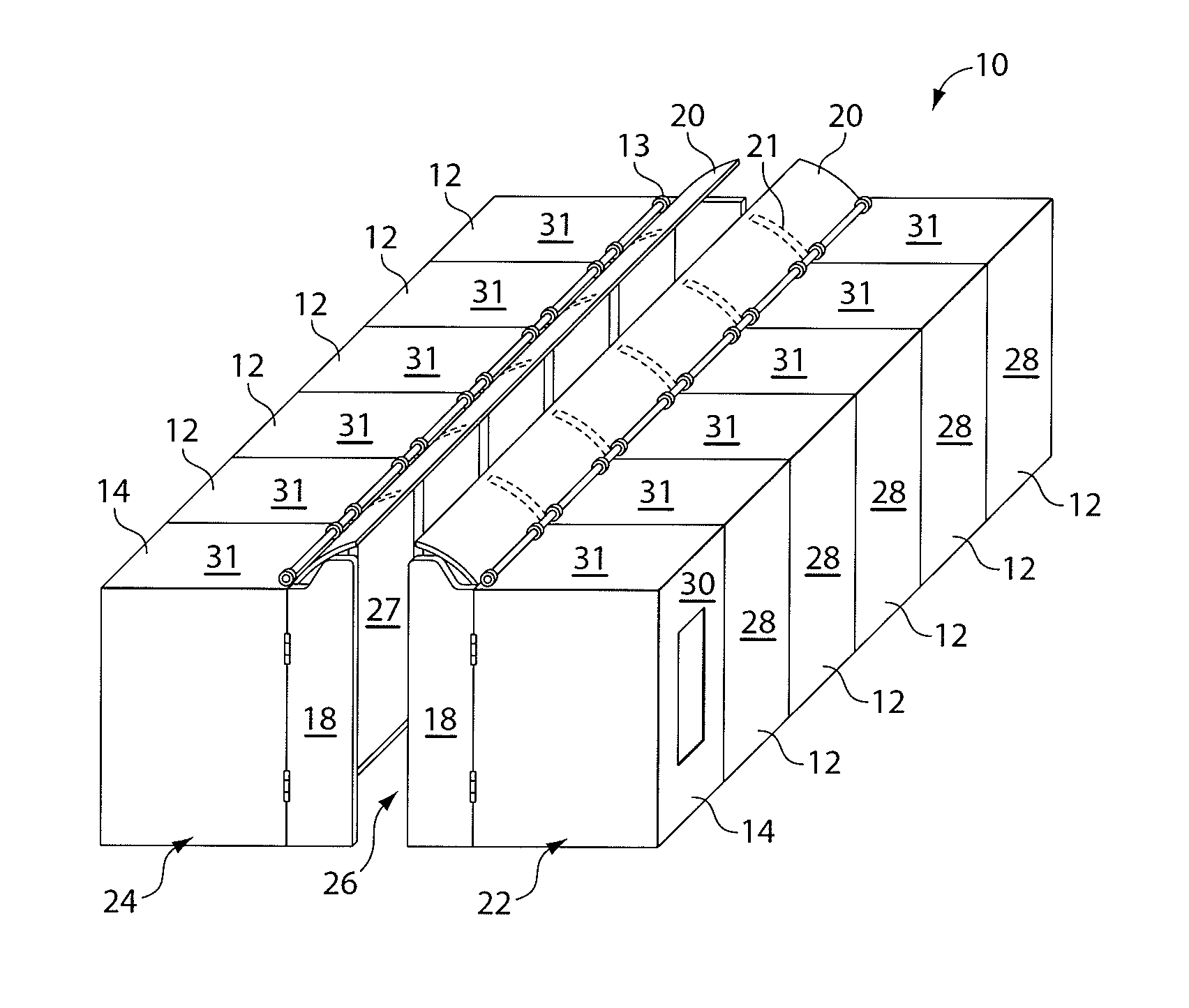
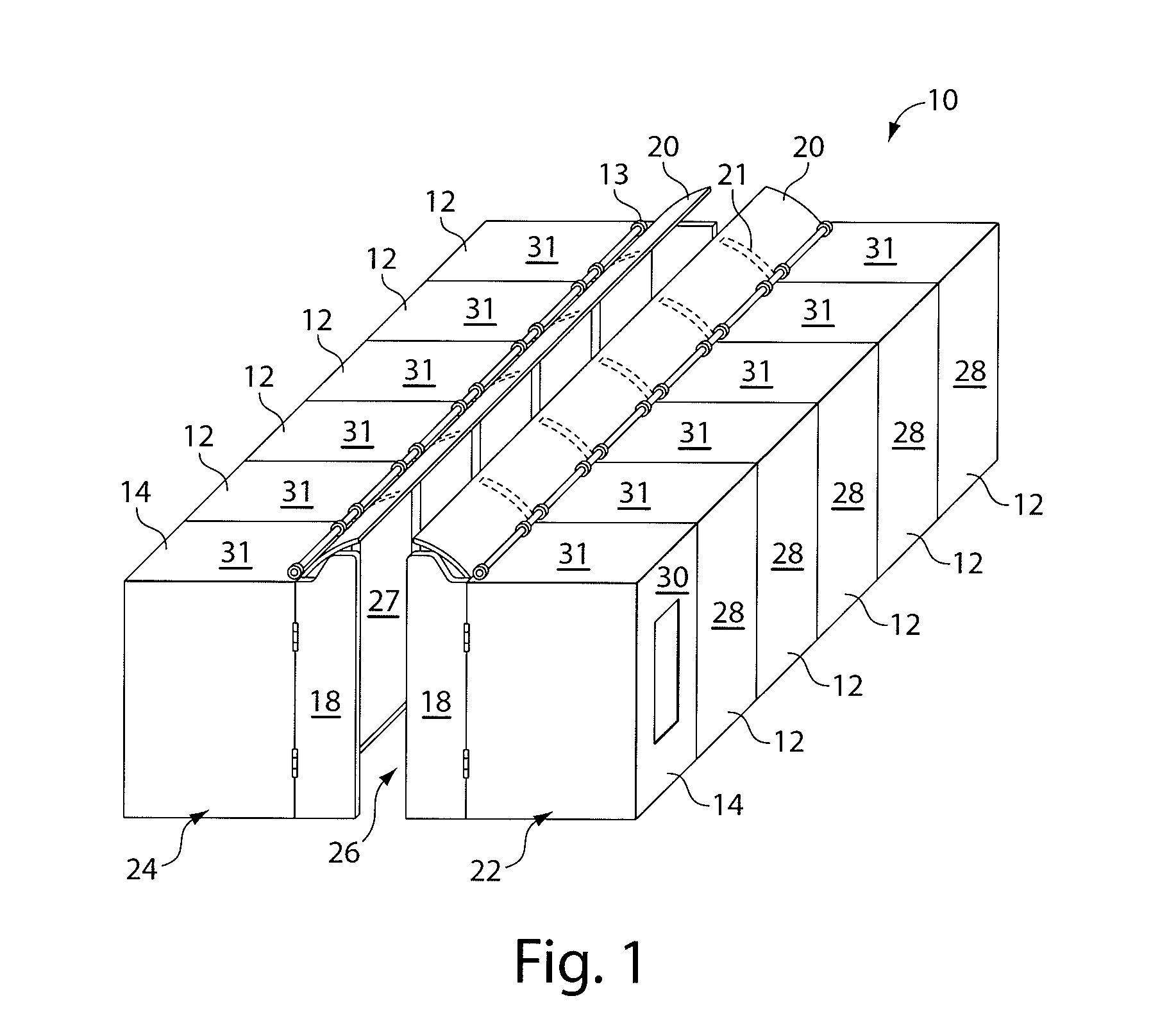
[0068] Embodiments of the invention provide techniques for cooling electronic equipment. Embodiments of the invention provide a modular cooling unit for cooling rack-mounted equipment, where the modular cooling unit provides a horizontally-moving stream of cool air to a row of rack enclosures by releasing cooled air from the cooling unit to be received along substantially the full height of the equipment racks. Embodiments of the invention may include a vertically-moving stream of cool air to a rack or a row of rack enclosures. Embodiments of the invention include air turning members to direct the air in a designated direction. Embodiments of the invention can include air flow restriction members positioned at various portions of the cooling unit and / or data center. Cooling is provided in some embodiments using redundant cooling units to help prevent downtime due to electrical or mechanical failures. Cooling can be provided in some embodiments using a cool air supply duct. Other emb...


PUM


Abstract

A data center includes an electronic equipment rack having a front face and a back face and a cooling unit positioned adjacent to the rack, the cooling unit having a front face and a back face, the cooling unit being configured to exhaust cooled air from the front face of the cooling unit to cool the rack. The cooling unit is configured to release the cooled air along a substantial portion of a height of the front face of the rack.

Description

RELATED APPLICATIONS [0001] This application is a continuation of prior U.S. application Ser. No. 11 / 025,567, filed Dec. 29, 2004, which is incorporated by reference herein in its entiretyFIELD OF THE INVENTION [0002] Embodiments of the invention are directed to cooling of electronic devices, and more particularly to cooling electronic devices held in equipment racks. BACKGROUND OF THE INVENTION [0003] Electronic equipment racks are generally designed to receive a number of electronic components arranged vertically in the rack, mounted on shelves, and / or to front and rear mounting rails. The electronic equipment may include, for example, printed circuit boards, communications equipment, computers, including computer servers, or other electronic components. [0004] Electronic equipment housed in racks produces a considerable amount of heat, which undesirably affects performance and reliability of the electronic equipment. Often the heat produced by the rack-mounted components is not e...

Claims


Application Information

Patent Timeline
Patent Type & Authority Applications(United States)
IPC IPC(8): H05K7/20
CPCH05K7/20745
Inventor GERMAGIAN, MARKVANGILDER, JAMESDUDEK, JASON
Owner AMERICA POWER CONVERSION CORP
Why Eureka
Try Eureka