Polarization conversion element, polarization illuminator, display using the same illuminator, and projector

a technology of polarizing illuminator and conversion element, which is applied in the direction of polarizing elements, optics, instruments, etc., can solve the problems of inability to excessively increase the refractive power of small lenses, limited emission area of real light sources, and inability to accurately detect the light beam emitted from the light source, etc., to achieve high color reproducibility, reduce the size of cooling devices, and prevent the effect of increasing the temperature of polarizing plates

Inactive Publication Date: 2007-12-25
SEIKO EPSON CORP
View PDF22 Cites 4 Cited by
  • Summary
  • Abstract
  • Description
  • Claims
  • Application Information

AI Technical Summary

Benefits of technology

[0034]By adopting the above structure, the projection display apparatusprojector of the present invention can effectively prevent a phenomenon in which other polarized beams polarized in a different direction mix into polarized beams of almost the same type polarized in the same direction. Therefore, when a polarizing plate is used to obtain a required polarized beam to be modulated by the modulating device, it is possible to prevent the increase in temperature of the polarizing plate caused by absorption of an unnecessary polarized beam, and to substantially simplify and reduce the size of a cooling device for cooling the polarizing plate. A liquid crystal device may be used as the modulating device.
[0035]According to the above structure, an incident beam is initially separated into a plurality of intermediate beams and the intermediate beams are finally superimposed on the modulating device. Therefore, even if the intensity distribution of the light emitted from the light source is very imbalanced in the cross section thereof, it is possible to obtain as illumination light polarized beams that are uniform in brightness and color. Consequently, it is possible to achieve a compact display apparatus capable of producing a display that is bright and uniform in brightness and color.
[0036]The projection display apparatusprojector fu...

Problems solved by technology

The optical system disclosed in Japanese Unexamined Patent Publication No. 7-294906 has, however, the following problems.
However, a real light source has a limited emission area.
Therefore, parallelism of the light beam emitted from the light source is not always good.
Consequently, it is impossible to excessively increase the refractive power of the small lens used for reducing the diameter of the beam.
For the above reasons, it is difficult to sufficiently reduce the diameter of the l...

Method used


Image

  • Polarization conversion element, polarization illuminator, display using the same illuminator, and projector
  • Polarization conversion element, polarization illuminator, display using the same illuminator, and projector
  • Polarization conversion element, polarization illuminator, display using the same illuminator, and projector

Examples


first embodiment

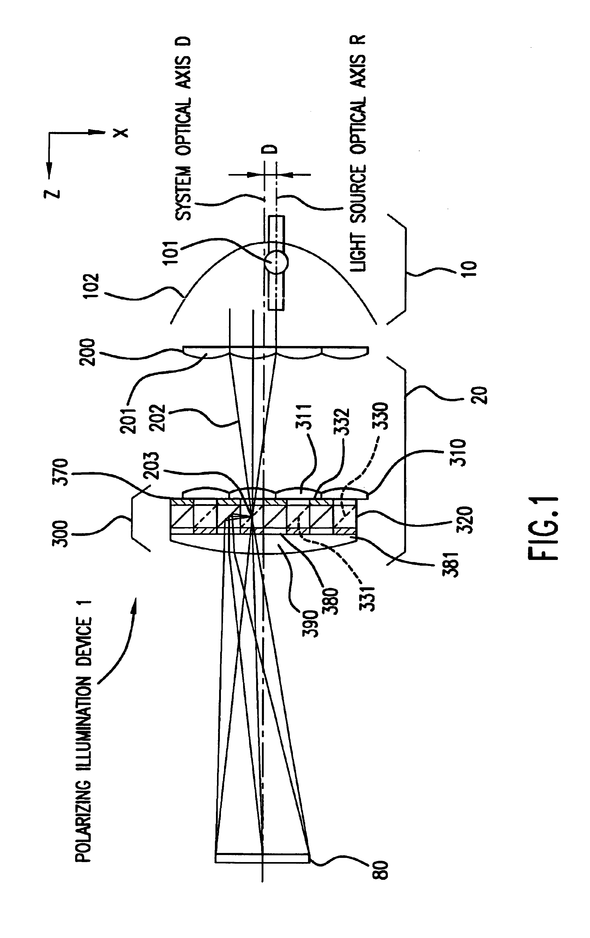
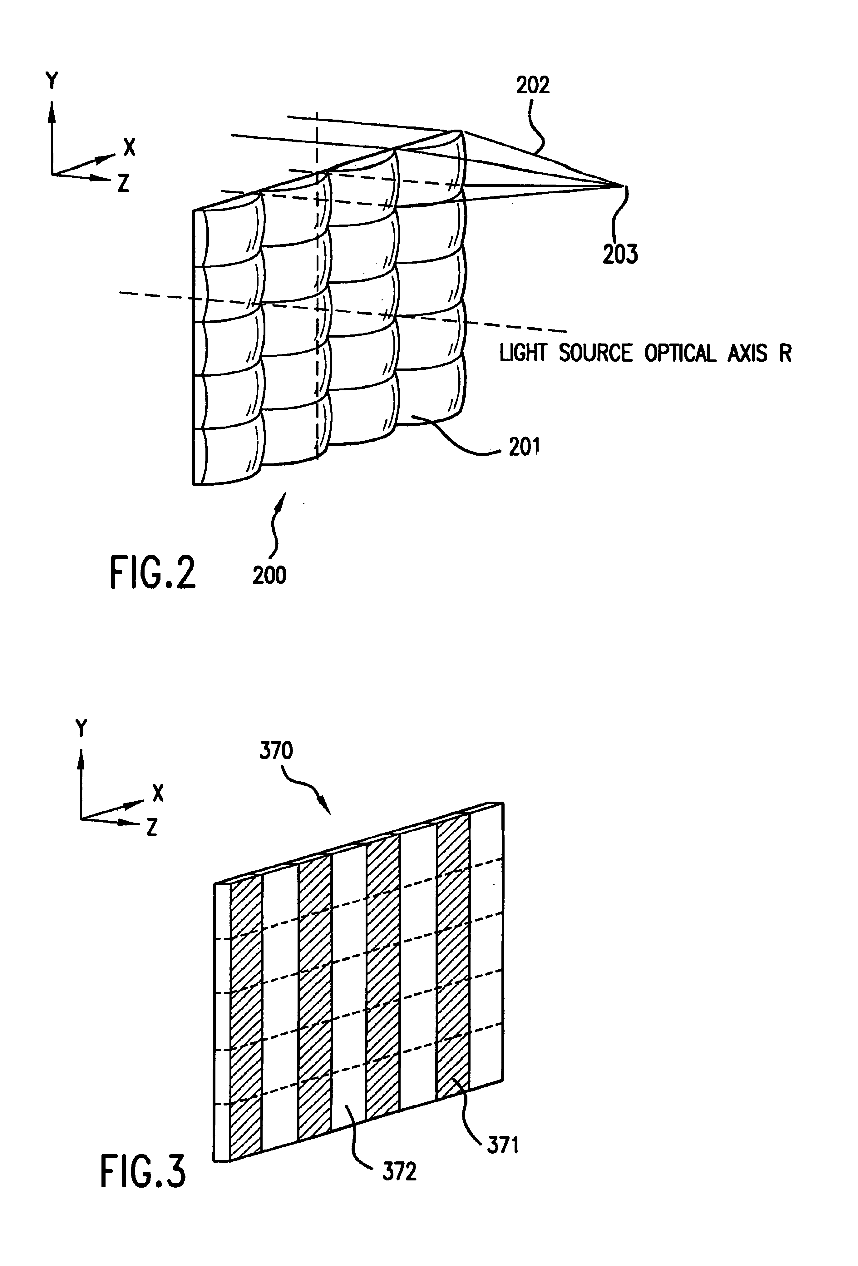
[0054]FIG. 1 is a schematic structural plan view of the principal part of a polarizing illumination device according to a first embodiment. FIG. 1 is a plan view in the XZ plane which passes through the center of a first optical element 200 which will be described later. The polarizing illumination device 1 of this embodiment generally comprises a light source section 10 and a polarized light generation device 20 that are arranged along a system optical axis L. Light beams emitted from the light source section 10 and polarized in random directions (hereinafter referred to as randomly polarized beams) are converted by the polarized light generating device 20 into the same type of polarized beams that are polarized in almost the same direction, and directed to an illumination region 90.

[0055]The light source section 10 generally comprises a light source lamp 101 and a parabolic reflector 102. Light radiated from the light source lamp is reflected by the parabolic reflector 102 in one ...

second embodiment

[0090]A description will be given of a direct-view display apparatus in which the polarizing illumination device 1 of the first embodiment is incorporated. In this embodiment, a transmission-type liquid crystal device is used as a modulating device for modulating light beams emitted from the polarizing illumination device according to display information.

[0091]FIG. 11 is a schematic structural view showing the principal part of an optical system of a display apparatus 2 according to this embodiment, and shows the sectional structure in the XZ plane. The display apparatus 2 of this embodiment roughly comprises the polarizing illumination device 1 shown described in the first embodiment, a reflecting mirror 510, and a liquid crystal device 520.

[0092]The polarizing illumination device 1 has a light source section 10 for emitting randomly polarized beams in one direction, and the randomly polarized beams emitted from the light source section 10 are converted into substantially the same ...

third embodiment

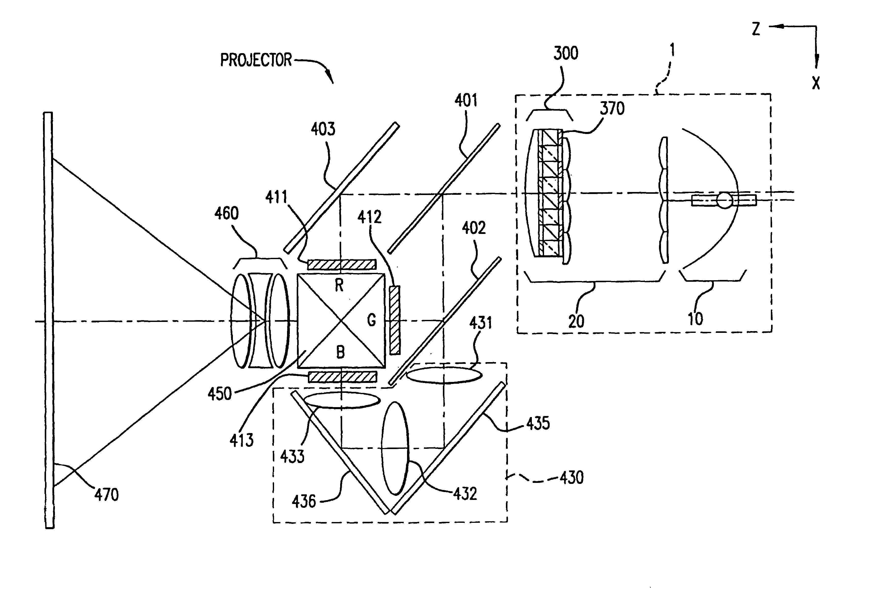
[0096]A description will be given of a first example of a projection display apparatusprojector in which the polarization illumination device 1 described in the first embodiment is incorporated. In this embodiment, a transmission-type liquid crystal device is used as a modulating device for modulating light beams emitted from the polarizing illumination device according to display information.

[0097]FIG. 12 is a schematic structural view showing the principal part of an optical system of a projection display apparatusprojector 3 according to this embodiment, and shows the sectional structure in the XZ plane. The projection display apparatusprojector 3 of this embodiment generally comprises the polarizing illumination device 1 described in the first embodiment, a colored light separating means for separating a white light beam into three colored lights, three transmission-type liquid crystal devices for modulating the colored lights according to display information and thereby forming...


PUM


Abstract

A polarizing conversion device in accordance with the invention includes a first optical element for condensing an incident beam and forming a plurality of intermediate beams spatially separated from one another, and a second optical element for spatially separating each intermediate beam into two polarized beams and aligning the polarization directions of the polarized beams, thereby obtaining the same type of polarized beams. In the second optical element, a shading plate is placed to prevent light from directly entering a section corresponding to a reflecting plane of a polarizing separation unit array. Since the ability of separating the intermediate beam into two polarized beams is thereby enhanced, it is possible to perform conversion into the same type of polarized beams polarized in the same direction, with high efficiency.

Description

BACKGROUND OF THE INVENTION[0001]1. Field of the Invention[0002]The present invention relates to a polarizing conversion device and a polarizing illumination device for generating, from incident light beams as randomly polarized beams, illuminating beams that have a more uniform light intensity distribution in an illumination region than that of the incident beams and are polarized in almost the same direction. Furthermore, the present invention relates to a display apparatus and a projection display apparatusprojector using these devices.[0003]2. Description of Related Art[0004]A polarizing illumination device capable of efficiently generating the same type of polarized light beams is ideal as an illuminating device for use in a display apparatus, such as a liquid crystal apparatus, which employs a panel for modulating polarized light beams. Accordingly, an illuminating optical system has been proposed that converts random polarized light beams emitted from a light source into the ...

Claims


Application Information

Patent Timeline
IPC IPC(8): G02B27/10G02B5/30G02B27/28G02F1/1335G02F1/13357
CPCG02B27/283G02B27/285G02F1/133536G02F1/13362G02F1/13355G02B27/28
Inventor ITOH, YOSHITAKAHASHIZUME, TOSHIAKI
Owner SEIKO EPSON CORP
Why Eureka
Try Eureka