Microfluidic ultrasonic particle separators with engineered node locations and geometries

a technology of microfluidic ultrasonic particle separator and engineered node location, which is applied in the direction of separation process, laboratory glassware, instruments, etc., can solve the problems of limited mixing, achieve greater purity, improve separation, and optimize the pressure field resulting from acoustic waves

Active Publication Date: 2015-03-31
LAWRENCE LIVERMORE NAT SECURITY LLC
View PDF4 Cites 5 Cited by
  • Summary
  • Abstract
  • Description
  • Claims
  • Application Information

AI Technical Summary

Benefits of technology

[0013]The present invention provides high-throughput sample processing of biological material. The system of the present invention separates out cell-sized particles from a background solution containing other biological materials (viruses, proteins nucleic acids, etc.) in order to allow uncontaminated analysis of either the background sample or the separated cells. The present invention uses the vibrations of a piezoelectric transducer to produce acoustic radiation forces within microfluidic channels. Whereas other investigators have demonstrated technologies that position a single stream of concentrated particles on the center-line of a fluid channel, or multiple streams of particles, such that some of them are off-center, the system of the present invention positions a single stream of concentrated particles off-center in the fluid channel. This is highly advantageous for achieving improved separation between the two sample fractions, and greater purity within each fraction. In one embodiment, the stream of concentrated particles is positioned off-center in the separation channel by means of subdividing the channel with one or more thin acoustically transparent walls. In another embodiment the stream of concentrated particles is positioned off-center n the fluid flow with the aid of a polymer gel structure positioned adjacent to the fluid channel. In these embodiments, or in any other, the pressure field resulting from the acoustic waves can be optimized by driving the piezoelectric transducer at multiple frequencies on a single device. Additionally, in these embodiments, or in any other, the separation channel can be routed in a serpentine fashion to pass multiple times (3, 5, etc.) through the ultrasound region, thereby providing a longer residence time for the sample in the acoustic field, increasing separation efficiency.
[0014]The present invention provides an ultrasonic microfluidic system for separating smaller particles from larger particles suspended in a sample fluid. This sample fluid flows down a separation channel, side-by-side with a “recovery buffer,” which is typically a fluid into which the larger particles of interest are to be transferred. The two fluid streams are in contact with each other, but mixing is limited only to diffusion due to the low Reynolds number of microfluidic flows. An acoustic transducer in contact with the microfluidic chip produces an ultrasound pressure field throughout these fluids. Properly tuned to match the geometric parameters of the channel, the acoustic transducer generates a resonant standing wave within the fluid, creating one or more zones of minimal pressure amplitude (acoustic nodes) toward which particles are driven. The forces that particles experience are dependent on particle, size; therefore, the largest particles move toward the node fastest. Positioning the node within the recovery fluid stream allows the largest particles to be carried out of the chip with the recovery fluid, separating them from other sample components that remain in the sample stream. In one embodiment a second fluid channel (“bypass channel”) is located substantially parallel to the separation channel. A wall that is thin enough to negligibly effect the transmission of ultrasound between the bypass and separation channel (“acoustically transparent wall”) is located between the two channels. In another embodiment the stream of concentrated particles is positioned off-center in the fluid channel by means of a gel positioned adjacent the fluid channel.

Problems solved by technology

The two fluid streams are in contact with each other, but mixing is limited only to diffusion due to the low Reynolds number of microfluidic flows.

Method used


Image

  • Microfluidic ultrasonic particle separators with engineered node locations and geometries
  • Microfluidic ultrasonic particle separators with engineered node locations and geometries
  • Microfluidic ultrasonic particle separators with engineered node locations and geometries

Examples


example 1

Single Node System

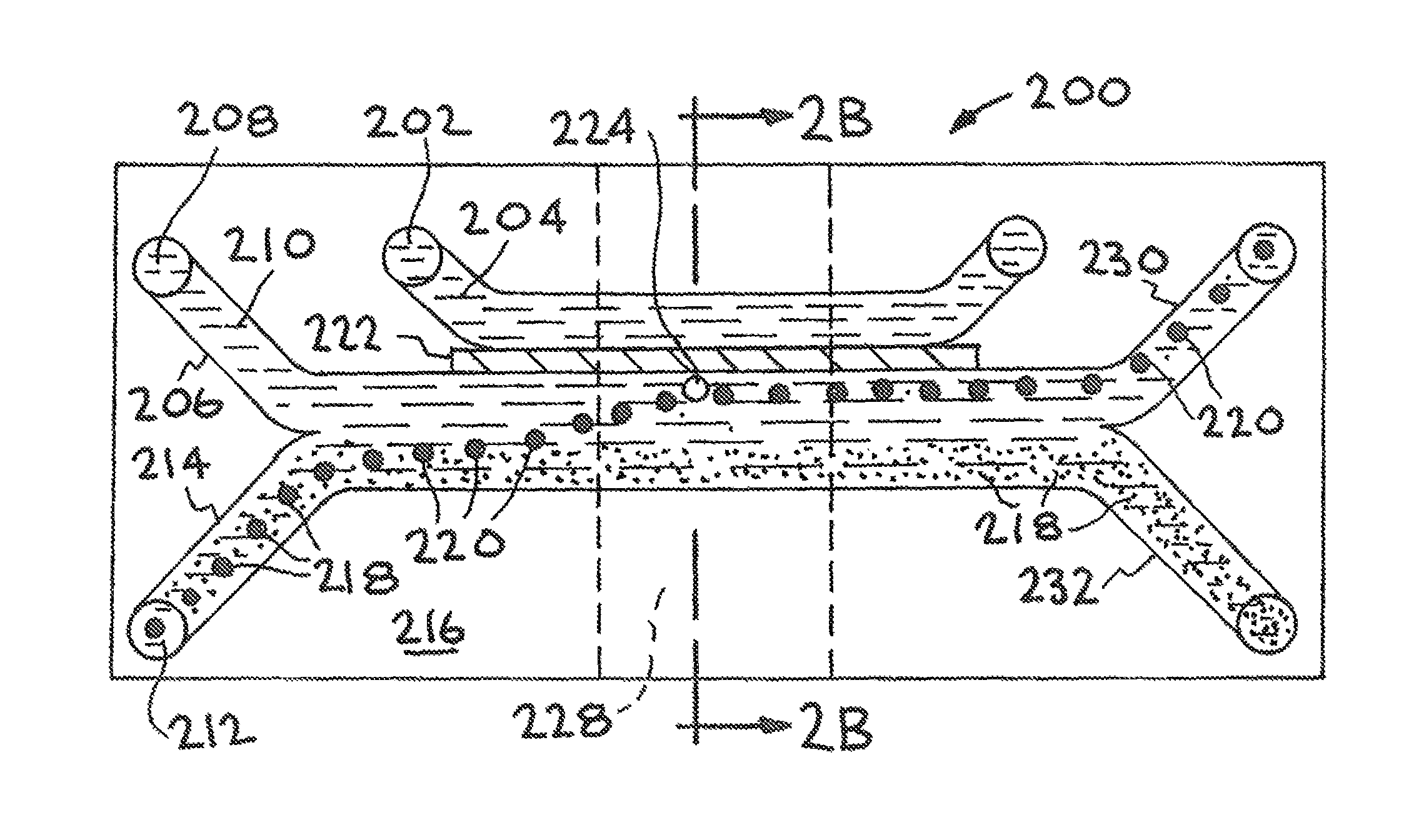
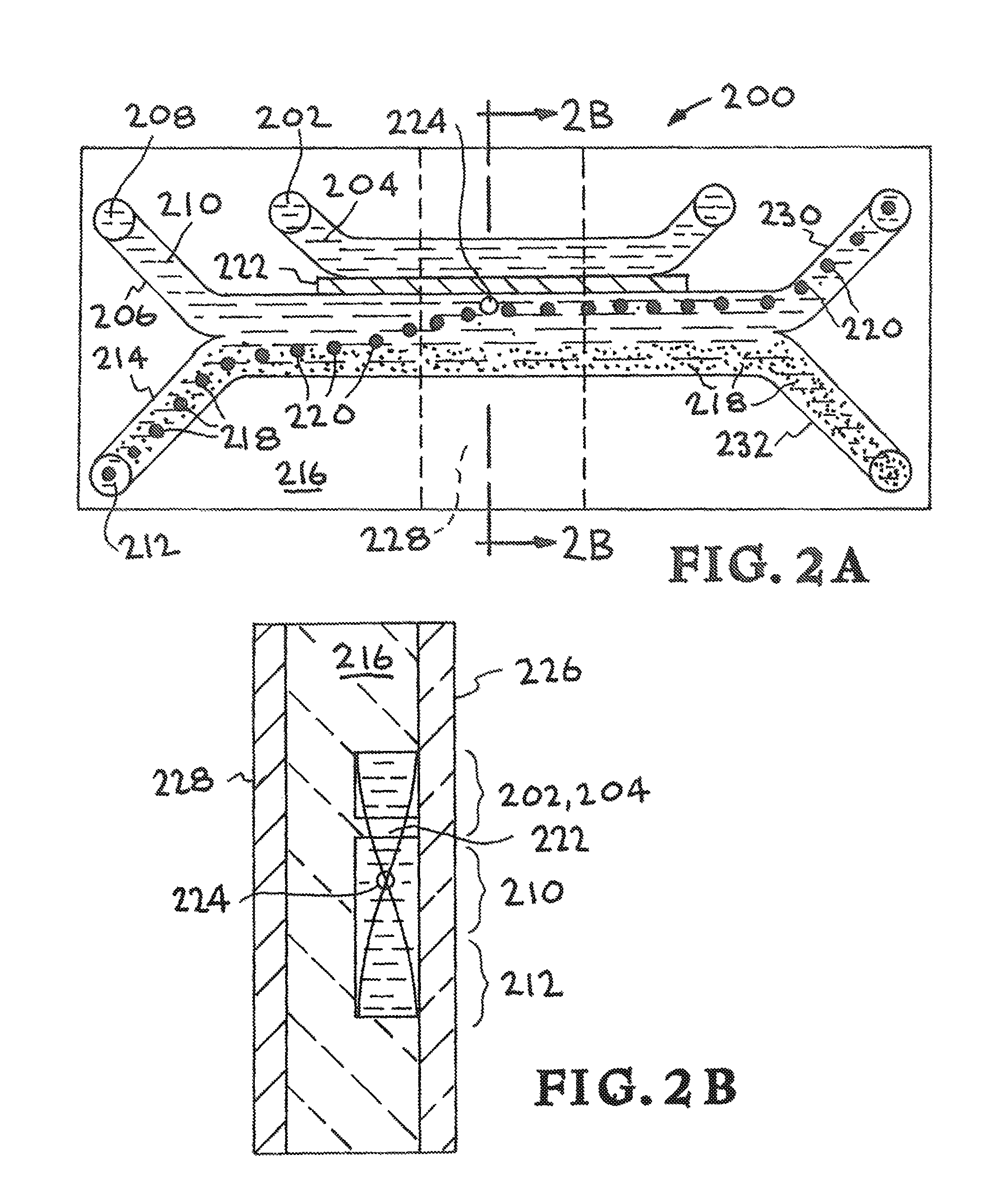
[0026]Referring now to the drawings and in particular to FIG. 2A, one embodiment of the present invention is illustrated.

[0027]The device uses multiple microfluidic channels running in parallel along the length of a microfluidic chip, separated by specifically-designed distances (the “wall thickness”). One of these multiple channels serves as the separation channel and has two inlets and two outlets. The ultrasound standing-wave pressure fields are optimized to transfer focused particles out of the sample stream and into the recovery fluid within the recovery fluid channel. The piezoelectric transducer may be driven at single or multiple frequencies to achieve the optimal node placement depending on the channel and wall geometry. In addition, multiple small piezoelectric transducers may be arranged to produce different sound fields in different regions of the chip.

[0028]The present invention provides an ultrasonic microfluidic system for separating smaller particle...

example 2

Two Node System

[0034]Referring now to FIG. 3A, another embodiment of the present invention is illustrated. The device uses multiple microfluidic channels running in parallel along the length of a microfluidic chip 316, separated by specifically-designed distances (the “wall thickness”). One of these multiple channels serves as the separation channel and has two inlets and two outlets. The ultrasound standing-wave pressure fields are optimized to transfer focused particles out of the sample stream and into the adjacent recovery fluid stream, which flow together down the separation channel. The piezoelectric transducer 314 may be driven at single or multiple frequencies to achieve the optimal node placement depending on the channel and wall geometry. In addition, multiple small piezoelectric transducers may be arranged to produce different sound fields in different regions of the chip.

[0035]The present invention provides an ultrasonic microfluidic system for separating smaller particl...

example 3

Alternative Fluid Channel Layout

[0042]Referring now to the drawings and in particular to FIG. 4A, another embodiment of the present invention is illustrated. The device uses multiple microfluidic channels running in parallel along the length of a microfluidic chip, separated by specifically-designed distances (the “wall thickness”). One of these multiple channels serves as the separation channel and has two inlets and two outlets. The ultrasound standing-wave pressure fields are optimized to transfer focused particles out of the sample stream and into the recovery fluid within the recovery fluid channel. The piezoelectric transducer may be driven at single or multiple frequencies to achieve the optimal node placement depending on the channel and wall geometry. In addition, multiple small piezoelectric transducers may be arranged to produce different sound fields indifferent regions of the chip.

[0043]The embodiment illustrated in FIG. 4A is designated generally by the reference numer...


PUM

PropertyMeasurementUnit
diameteraaaaaaaaaa
depthaaaaaaaaaa
thicknessaaaaaaaaaa

Abstract

An ultrasonic microfluidic system includes a separation channel for conveying a sample fluid containing small particles and large particles, flowing substantially parallel, adjacent to a recovery fluid, with which it is in contact. An acoustic transducer produces an ultrasound standing wave, that generates a pressure field having at least one node of minimum, pressure amplitude. An acoustic extension structure is located proximate to said separation channel for positioning said acoustic node off center in said acoustic area and concentrating the large particles in said recovery fluid stream.

Description

CROSS-REFERENCE TO RELATED APPLICATIONS[0001]The present application is a divisional of pending U.S. application Ser. No. 13 / 571,640 filed Aug. 10, 2012, which is a non-provisional application of U.S. Provisional Patent Application No. 61 / 524,020 filed Aug. 16, 2011, the entire contents and disclosures of which are specifically incorporated by reference herein.STATEMENT AS TO RIGHTS TO INVENTIONS MADE UNDER FEDERALLY SPONSORED RESEARCH AND DEVELOPMENT[0002]The United States Government has rights in this invention pursuant to Contract No. DE-AC52-07NA27344 between the United States Department of Energy and Lawrence Livermore National Security, LLC for the operation of Lawrence Livermore National Laboratory.BACKGROUND[0003]1. Field of Endeavor[0004]The present invention relates to microfluidic particle separators and more particularly to microfluidic ultrasonic particle separators with engineered node locations and geometries.[0005]2. State of Technology[0006]The article, “Chip integr...

Claims


Application Information

Patent Timeline
Patent Type & Authority Patents(United States)
IPC IPC(8): B03B5/00B01D21/28B01L3/00G01N33/487G01N33/49
CPCB01D21/28B01D21/283B01L3/502761G01N33/491G01N33/48728B01D2221/10B01L2200/0636B01L2200/0652B01L2300/0816B01L2300/0864B01L2400/0439B01L2400/0487B01L3/50273B01L2200/0631G01N1/4077G01N2001/4094
Inventor ROSE, KLINT A.FISHER, KARL A.WAJDA, DOUGLAS A.MARIELLA, JR., RAYMOND P.BAILEY, CHRISTOPHERDEHLINGER, DIETRICHSHUSTEFF, MAXIMJUNG, BYOUNGSOKNESS, KEVIN D.
Owner LAWRENCE LIVERMORE NAT SECURITY LLC
Why Eureka
Try Eureka