Hierarchical Hydrophilic/Hydrophobic Micro/Nanostructures for Pushing the Limits of Critical Heat Flux

a hydrophilic/hydrophobic micro/nanostructure technology, applied in indirect heat exchangers, laminated elements, lighting and heating apparatus, etc., can solve the problems of low cost and reliability, high heat flux dissipation has become critical, and the use of microchannels for single-phase cooling has been pursued but limited, so as to achieve easy balance of liquid introduction rate and alleviate flow instabilities , the effect of modifying the location and shape of the meniscus

Active Publication Date: 2016-10-06
UNIV OF FLORIDA RES FOUNDATION INC
View PDF13 Cites 5 Cited by
  • Summary
  • Abstract
  • Description
  • Claims
  • Application Information

AI Technical Summary

Benefits of technology

[0006]Embodiments of the invention are directed to heat sinks that have a liquid fluid entrance but a vapor fluid exit, where the vapor quality is 100%. The heat sink can employ a nanofiber membrane through which vapor readily passes but liquid is constrained by the nanoporous membrane. The device employs trenches that supply liquid refrigerant to an active area where fins support the membrane from which refrigerant exits as a vapor to a condenser. The rate of liquid introduction is readily balanced with the vapor exit to be of service over an extremely wide range of heat loads. The device employs a new two-phase cooling approach that is based on phase change over a predefined meniscus. The heat sink utilizes micro-engineered-structures to form a capillary-controlled meniscus separating liquid and vapor fields at specific locations. This configuration maintains stable liquid-vapor interface over a large area to employ thin film evaporation mode of heat transfer while alleviating flow instabilities.
[0007]Embodiments of the invention are directed to two-phase heat sinks that utilize thin film evaporation over a predefined liquid-vapor interface as the main mode of heat transfer. In one embodiment, liquid and vapor microchannels are separated with arrays of equi-spaced posts, which act as capillary forced valves and limit mixing of liquid and vapor phases. The location and shape of the meniscus can be altered by the device geometry, surface characteristics, and liquid pressure at the interface. In this manner, instability issues associated with randomly-moving evaporative interface in boiling can be significantly reduced.

Problems solved by technology

The primary mode of heat transfer for several decades has been single-phase cooling due to its low cost and reliability.
Very high heat flux dissipation has become critical for miniaturized electronics with increased chip power densities.
The use of microchannels for single-phase cooling has been pursued but is limited by the high chip temperature and large pumping power required.
The traditional single-phase heat sinks are no longer capable of dissipating the generated heat in such applications.
Phase change heat sinks where boiling of a solvent is carried out has the ability to dissipate large quantities of heat.
Flow instability, low heat transfer coefficient, and flow misdistribution have resulted in poor performance of two-phase systems.
However, high cooling rates have only been achieved with high surface superheating, high mass flux, low heat transfer coefficients, and / or low vapor exit quality.
Although improvements in the heat transfer characteristics of boiling at microscale have been reported, the nature of the boiling process is not altered and, hence, the problems associated with boiling could not be eliminated.
Dynamic and static instability issues associated with boiling at microscale and identified random nucleation, sudden growth of bubbles and moving evaporating thin film liquid is the cause of these instabilities and whenever liquid-vapor interfaces are rapidly disrupted, flow instability issues are intensified.

Method used


Image

  • Hierarchical Hydrophilic/Hydrophobic Micro/Nanostructures for Pushing the Limits of Critical Heat Flux
  • Hierarchical Hydrophilic/Hydrophobic Micro/Nanostructures for Pushing the Limits of Critical Heat Flux
  • Hierarchical Hydrophilic/Hydrophobic Micro/Nanostructures for Pushing the Limits of Critical Heat Flux

Examples


Embodiment Construction

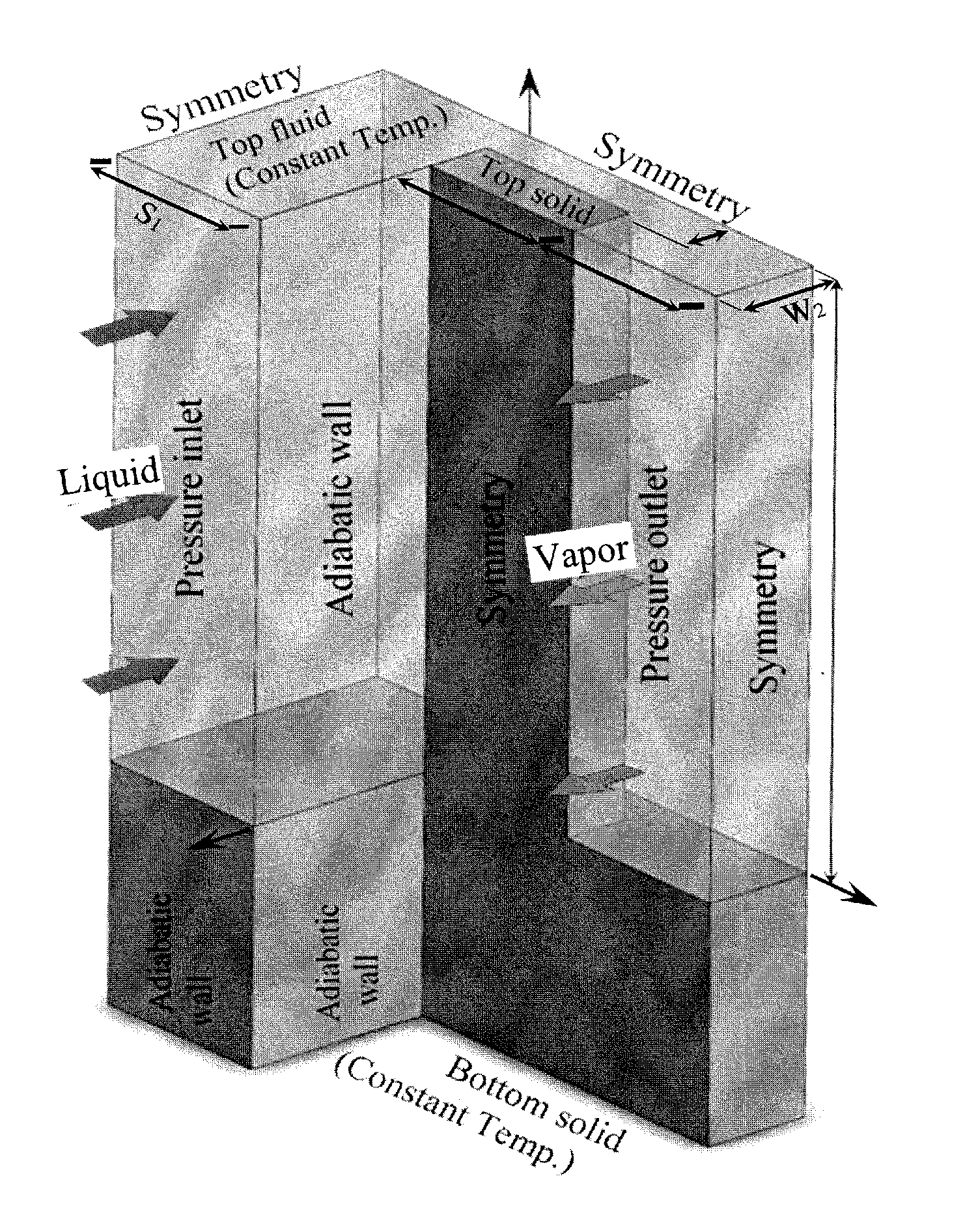
[0053]Embodiments of the invention are directed to heat sinks that require, but are not limited to, a single liquid fluid inlet and have exclusively a vapor fluid outlet through a membrane. The liquid fluid portion of a heat sink, according to an embodiment of the invention, is illustrated in FIG. 1. The fluid can be any fluid, ranging from water through hydrofluorocarbon refrigerants, for example: trifluoromethane, difluoromethane, fluoromethane, pentafluoroethane, pentafluorodimethyl ether, 1,1,2,2-tetrafluoroethane, 1,1,1,2-tetrafluoroethane, bis(difluoromethyl)ether, 1,1,2-trifluoroethane, 1,1,1-trifluoroethane, methyl trifluoromethyl ether, 2,2,2-trifluoroethyl methyl ether, 1,2-difluoroethane, 1,1-difluoroethane, fluoroethane, 1,1,2,2,3,3,3-heptafluoropropane, trifluoromethyl 1,1,2,2-tetrafluoroethyl ether, 1,1,1,2,3,3,3-heptafluoropropane, trifluoromethyl 1,2,2,2-tetrafluoroethyl ether, 1,1,1,2,2,3-hexafluoropropane, 1,1,1,2,3,3-hexafluoropropane, 1,1,1,3,3,3-hexafluoropropan...


PUM

PropertyMeasurementUnit
period of timeaaaaaaaaaa
boiling pointaaaaaaaaaa
contact angleaaaaaaaaaa

Abstract

A high efficiency heat sink for the cooling of microelectronic devices involves a phase change from liquid fluid to fluid vapor with a vapor quality of 100%. The liquid fluid is provided to an active area that contains fins having micrometer dimension that support a membrane that is nanoporous. The membrane is effectively impermeable to liquid fluid but permeable to fluid vapor. The heat sink provides very high heat flux and coefficient of heat transfer at low mass flux over a broad range of surface superheat temperatures. The heat sink can be constructed of equi-spaced posts that separate liquid microchannels from vapor microchannels that are connected through capillary forced valves formed between adjacent equi-spaced posts.

Description

CROSS-REFERENCE TO RELATED APPLICATIONS[0001]This application is a continuation-in-part of International Application No. PCT / US2014 / 070903, filed Dec. 17, 2014, which claims priority to U.S. Provisional Application Ser. No. 61 / 917,177, filed Dec. 17, 2013, which is hereby incorporated by reference herein in their entireties, including any figures, tables, or drawings.BACKGROUND OF INVENTION[0002]The primary mode of heat transfer for several decades has been single-phase cooling due to its low cost and reliability. Very high heat flux dissipation has become critical for miniaturized electronics with increased chip power densities. The use of microchannels for single-phase cooling has been pursued but is limited by the high chip temperature and large pumping power required. The traditional single-phase heat sinks are no longer capable of dissipating the generated heat in such applications. As a result, introduction of innovative thermal management methods is desired to address the dem...

Claims


Application Information

Patent Timeline
Patent Type & Authority Applications(United States)
IPC IPC(8): H05K7/20H01L23/427H01L23/367F28D15/02
CPCH05K7/20309F28D15/025H01L23/3675H05K7/20318H05K7/20327H01L23/427F28F3/02F28F2245/04F28F13/187F28D15/046F28F2255/20H01L2924/0002H01L2924/00
Inventor MOGHADDAM, SAEEDFAZELI, SEYYED A.
Owner UNIV OF FLORIDA RES FOUNDATION INC
Why Eureka
Try Eureka