
Active power filter including power unit and its control method

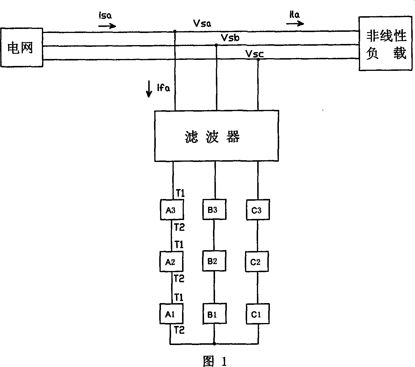
A power filter and power unit technology, applied in the field of active power filter and its control, can solve the problem that the DC voltage of the power unit cannot be controlled at a certain set value, the DC bus voltage deviates from the given value, and there is no power unit. Redundant functions and other issues, to achieve the effect of continuous operation, reducing impact, and solving the problem of inrush current

Inactive Publication Date: 2007-10-10
上海艾帕电力电子有限公司
View PDF2 Cites 90 Cited by
  • Summary
  • Abstract
  • Description
  • Claims
  • Application Information

AI Technical Summary

Problems solved by technology

When the characteristics and working conditions of the power units are different, even if the pulse rotation method is adopted, the DC bus voltage of other power units does not form a closed-loop control, and the DC bus voltage of other power units will still deviate from the given value.
[0008] 2. The output terminal of the inverter is directly connected to the power grid after passing through the filter. When the active power filter is powered on for the first time, the surge current caused by the charging of the internal capacitor of the power unit may cause damage to the active power filter
[0009] 3. When any power unit in the inverter fails, the entire active power filter will stop working, and there is no power unit redundancy function
[0011] This invention can realize the balance of the DC bus voltage of different power units, but it cannot control the DC voltage of the power units at a certain set value
In addition, there is no freewheeling diode at the two ends of the discharge resistor in this invention. When the parasitic inductance in the resistor is large, the surge voltage generated during the shutdown process of the IGBT for DC bus adjustment may cause the IGBT to be damaged by overvoltage.

Method used


Image

  • Active power filter including power unit and its control method
  • Active power filter including power unit and its control method
  • Active power filter including power unit and its control method

Examples


Embodiment Construction

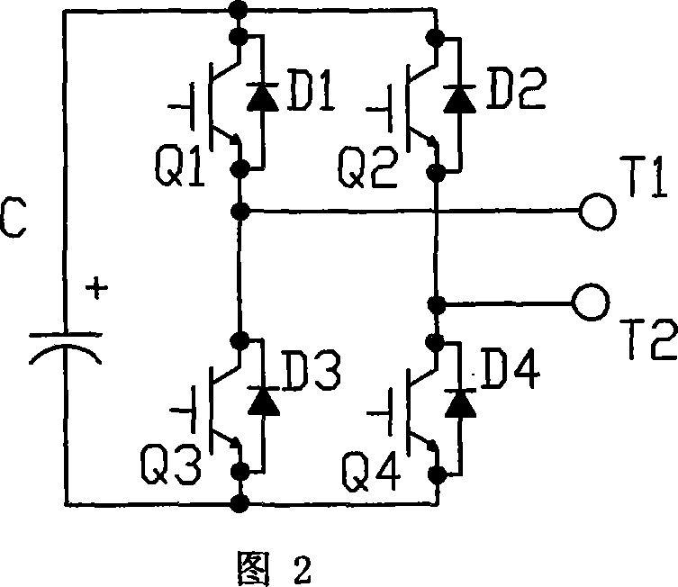
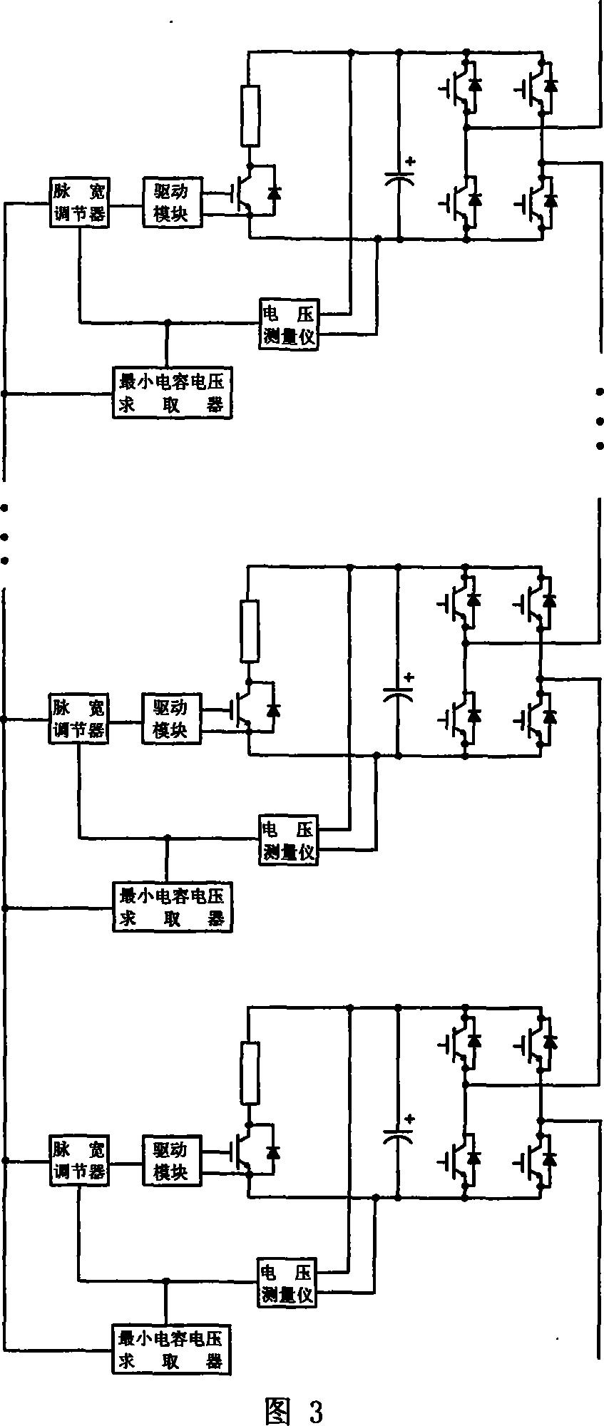
[0060] Fig. 4 is a power unit with a chopping energy consumption circuit used in an active power filter according to the present invention. The power unit consists of four power devices to form an H-bridge inverter circuit. The DC link uses capacitors for filtering and energy storage. The two ends of the DC bus of the power unit are connected in parallel with chopper energy consumption circuits to realize the control of the DC bus voltage of the power unit.

[0061] The power electronic devices Q1-Q4 of the power unit can use IGBT, MOSFET, IGCT, IEGT and other devices, and IGBT is taken as an example for illustration. Use pulse width modulation (PWM) and other methods to realize the inversion process of DC to AC, and output the required AC voltage. The four power electronic devices Q1~Q4 used for inverter are connected in antiparallel with four freewheeling diodes D1~D4 respectively, as shown in Figure 4. Generally speaking, the existing commercial IGBT modules have packaged ...


PUM


Abstract

The power unit includes H bridge inverter circuit, capacitance in DC section connected to DC bus in inverter circuit, and control circuit for controlling operation of the power unit. The power unit also includes a clipping energy consumption circuit. Combining a small quantity of active power absorbed by active electric power filter, the method realizes controlling DC bus voltage of power unit. The active electric power filter includes following parts: inverter with each phase including at least one power unit; voltage detection circuit, central control system, filtering circuit, precharge circuit, income line switch, interface and communication circuit, and cooling unit etc.

Description

technical field [0001] The invention relates to an active power filter including a power unit and a control method thereof. Background technique [0002] Due to the increase of various non-linear electrical loads, such as frequency converters, rectifiers, electric arc furnaces, and converters for high-voltage direct current transmission, the harmonic pollution of the power grid, power factor drop, voltage asymmetry, power supply interruption, voltage fluctuations and Problems such as flicker are becoming more and more prominent. [0003] Chapter 7 of "Harmonic Suppression and Reactive Power Compensation" (ISBN 7-111-06298-1 / TM.728) of China Machinery Industry Press introduces active power filters for low-voltage power supply grids. The active power filter is a new type of power electronic device used to dynamically suppress harmonics and compensate reactive power. It can quickly compensate harmonics that vary in size and frequency and reactive ...

Claims


Application Information

Patent Timeline
Patent Type & Authority Applications(China)
IPC IPC(8): H02J3/01H02J3/18G05F1/70
CPCY02E40/22Y02E40/40H02M2007/4835H02M1/32H02M7/4835
Inventor 竺伟
Owner 上海艾帕电力电子有限公司
Learn More