Flow distribution module and a stack of flow distribution modules

a technology of flow distribution module and stack, which is applied in the field of flow distribution module, can solve the problems of degrading the operation of semiconductor devices and consuming a lot of space on devices

Inactive Publication Date: 2010-11-16
DANFOSS SILICON POWER
View PDF35 Cites 95 Cited by
  • Summary
  • Abstract
  • Description
  • Claims
  • Application Information

AI Technical Summary

Benefits of technology

[0009]It is, thus, an object of the present invention to provide a cooling unit which is capable of providing cooling to several surfaces without resulting in a bulky device.
[0010]It is a further object of the present invention to provide a cooling unit which may be individually adapted to a specific cooling need without requiring specially manufactured parts.
[0011]It is an even further object of the present invention to provide a cooling unit which is simple to manufacture, yet being very flexible in terms of meeting specific demands or needs.

Problems solved by technology

For example, semiconductor devices generate heat during their operation, and this heat acts to degrade the operation of the semiconductor device.
This is a disadvantage since such a device will be rather space consuming in two dimensions.

Method used


Image

  • Flow distribution module and a stack of flow distribution modules
  • Flow distribution module and a stack of flow distribution modules
  • Flow distribution module and a stack of flow distribution modules

Examples


second embodiment

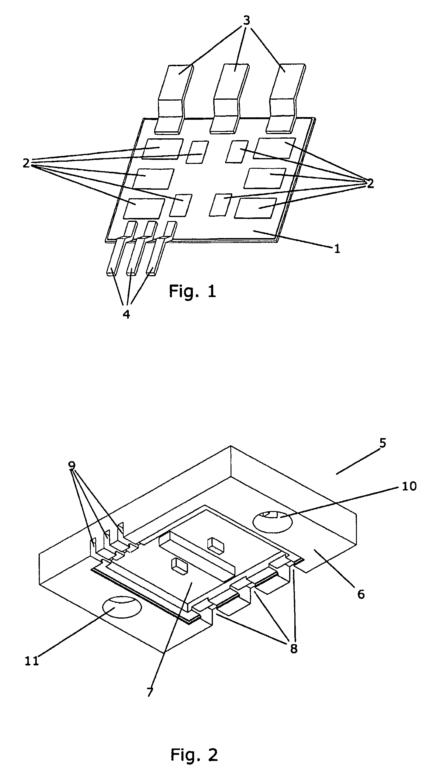
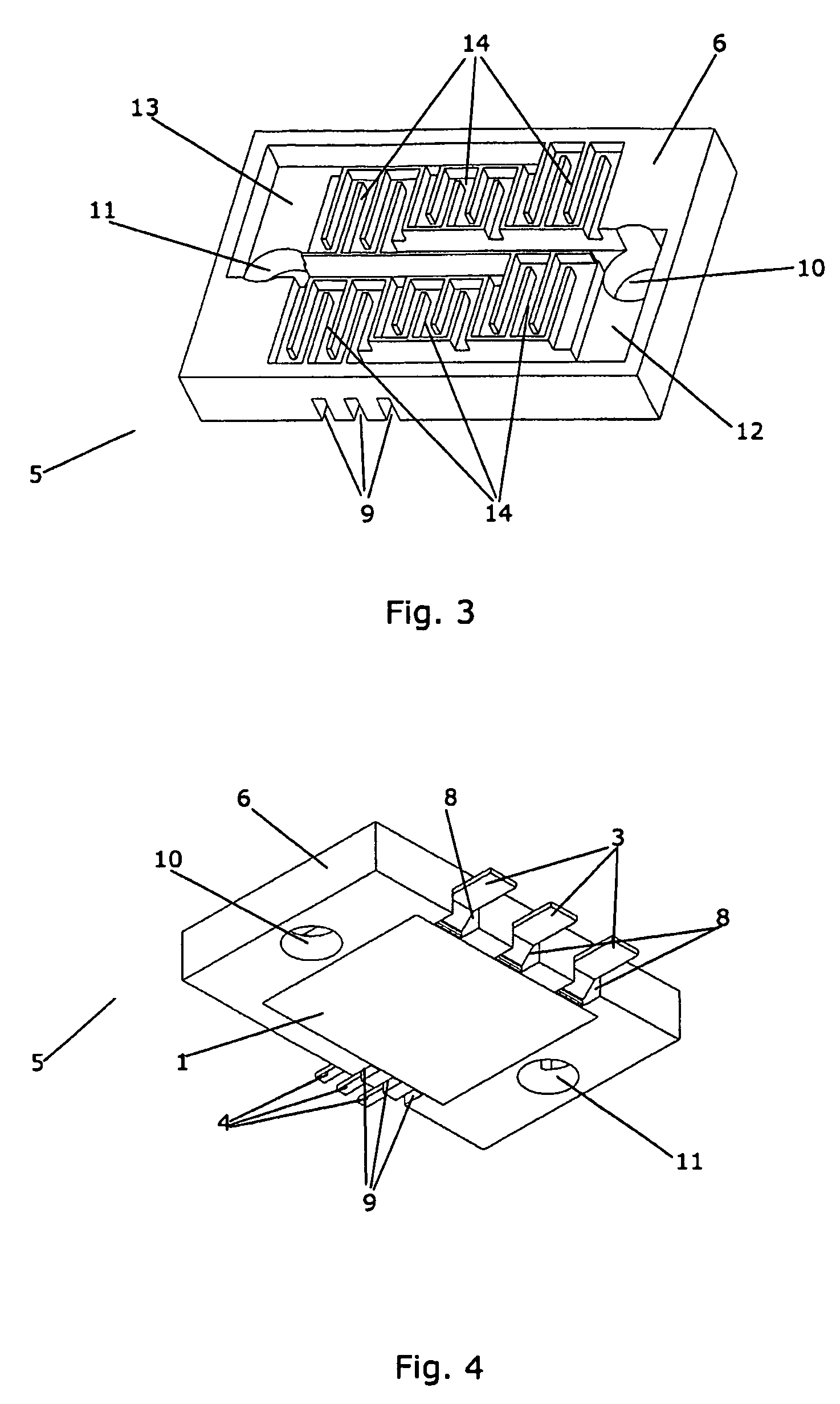
[0092]FIG. 19 shows a flow distribution module 5 according to the invention. The flow distribution module comprises a housing 6 with an inlet opening 10, an outlet opening 11, an inlet manifold 12, and outlet manifold 13 and six flow cells 14 formed therein. Each of the flow cells 14 establishes a fluid connection between the manifolds 12, 13 as described above.

[0093]FIG. 20 shows the flow distribution module 5 of FIG. 19 with a substrate part 19 mounted thereon in such a manner that the substrate part 19 forms an integral part of the housing 6. Three power terminals 3 and six control terminals 4 protrude from the substrate part 19. When another identical flow distribution module 5 is positioned on top of the flow distribution module 5 shown in FIG. 20, the flow cells 14 will pass a flow of fluid over the substrate part 19 of the upper flow distribution module 5, thereby providing cooling for that substrate part 19.

[0094]FIG. 21 is an exploded view of a stack of flow distribution mo...

third embodiment

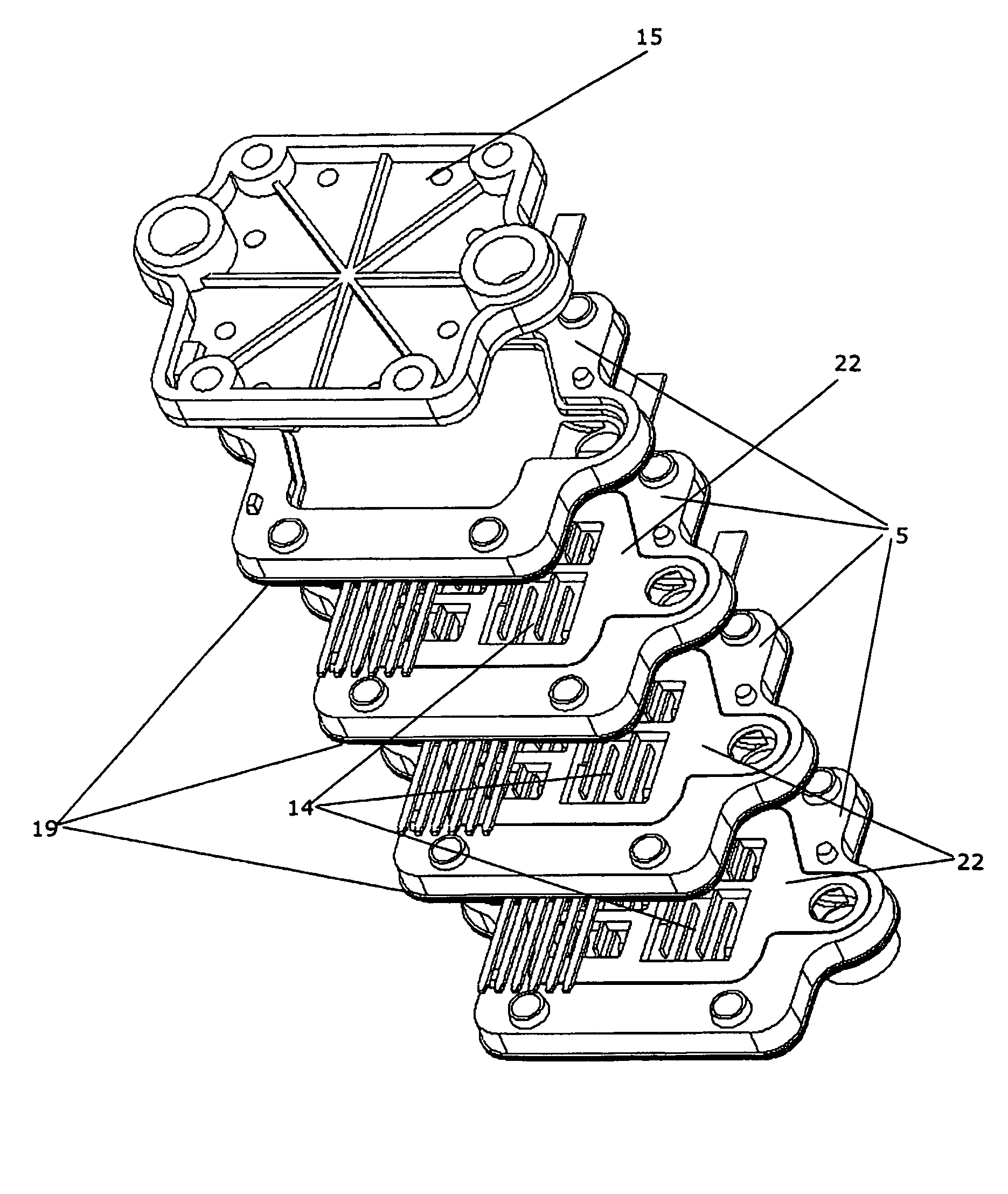
[0095]FIG. 22 is an exploded view of a flow distribution module 5 according to the invention with a substrate part 19 mounted thereon in such a manner that the substrate part 19 forms an integral part of a housing 6. Three power terminals 3 and six control terminals 4 protrude from the substrate part 19. The flow distribution module 5 comprises a housing 6 having an inlet opening 10, an outlet opening 11 and a cavity 21 formed therein. The cavity 21 is adapted to receive a separate baffle 22 having four flow cells 14 formed therein. On the side of the baffle 22 which faces downwards on the Figure, an inlet manifold and an outlet manifold are formed. Each of the flow cells 14 is fluidly connected to the inlet manifold via a cell inlet 23 and fluidly connected to the outlet manifold via a cell outlet 24, and each of the flow cells 14 thereby establishes a fluid connection between the inlet manifold and the outlet manifold.

[0096]FIG. 23 is an exploded view of a stack of flow distributi...

fourth embodiment

[0098]FIG. 25 is an exploded view of a flow distribution module 5 according to the invention. The flow distribution module 5 comprises a first part 25 having an inlet opening 10, an outlet opening 11, an inlet manifold 12, an outlet manifold 13 and a number of flow cells 14 formed therein. The flow distribution module 5 further comprises a second part 26 having an opening 27 formed therein. The second part 26 is further provided with two connector parts 28 which are used for connecting the flow distribution module 5 to another identical (or substantially identical) flow distribution module 5.

[0099]FIG. 26 shows the flow distribution module 5 of FIG. 25. The first 25 and the second 26 parts have been assembled, and the opening 27 is positioned corresponding to the flow cells 14. Thereby the flow cells 14 may distribute a flow of fluid over a surface which can be mounted in that area.

[0100]FIG. 27 is an exploded view of the flow distribution module 5 of FIGS. 25 and 26 and a standard ...


PUM


Abstract

A flow distribution module (5) for distributing a flow of cooling fluid across a surface. Is adapted to be connected to another at least substantially identical module (5). Makes it possible to provide a cooling unit which may be customized to meet specific cooling needs without requiring special adaptation of the ‘building blocks’. Thereby provides a flexible, yet simple, system. Furthermore a stack of flow distribution modules (5). Provides a very compact cooling unit when cooling is needed for several surfaces, no need for a cooling unit having a large surface area because the modules may be stacked in stead of positioned side-by-side.

Description

CROSS REFERENCE TO RELATED APPLICATIONS[0001]This application is entitled to the benefit of and incorporates by reference essential subject matter disclosed in International Patent Application No. PCT / DK2005 / 000746 filed on Nov. 22, 2005; Danish Patent Application No. PA 2004 01832 filed Nov. 24, 2004; and Danish Patent Application No. PA 2005 01196 filed Aug. 29, 2005.[0002]1. Field of the Invention[0003]The present invention relates to a flow distribution module for distributing a flow of fluid over a surface to be cooled. It further relates to a stack of such flow distribution modules.[0004]2. Background of the Invention[0005]It is sometimes desirable to be able to cool a surface of a heat generating object. For example, semiconductor devices generate heat during their operation, and this heat acts to degrade the operation of the semiconductor device. For power semiconductor devices it is necessary to provide cooling during operation in order to maintain acceptable device perform...

Claims


Application Information

Patent Timeline
Patent Type & Authority Patents(United States)
IPC IPC(8): H05K7/20H01L23/36
CPCH01L23/473H01L25/117H05K7/20927H01L2924/0002H01L2924/00
Inventor OLESEN, KLAUS KRISTEN
Owner DANFOSS SILICON POWER
Why Eureka
Try Eureka