Electronically variable analog delay line

A delay line, variable technology, applied in delay lines, circuits, electrical components, etc., can solve problems such as reducing signal-to-noise ratio, multi-operation power, etc.

Active Publication Date: 2016-12-28
TEKTRONIX INC
View PDF17 Cites 0 Cited by
  • Summary
  • Abstract
  • Description
  • Claims
  • Application Information

AI Technical Summary

Problems solved by technology

This method is compatible with standard integrated chip (IC) processes, but degrades the signal-to-noise ratio due to noise generation in the active phase and may require more operating power than other methods

Method used


Image

  • Electronically variable analog delay line
  • Electronically variable analog delay line
  • Electronically variable analog delay line

Examples


Embodiment Construction

[0014] In the drawings, which are not necessarily to scale, identical or corresponding elements of the disclosed systems and methods are indicated by identical reference numerals.

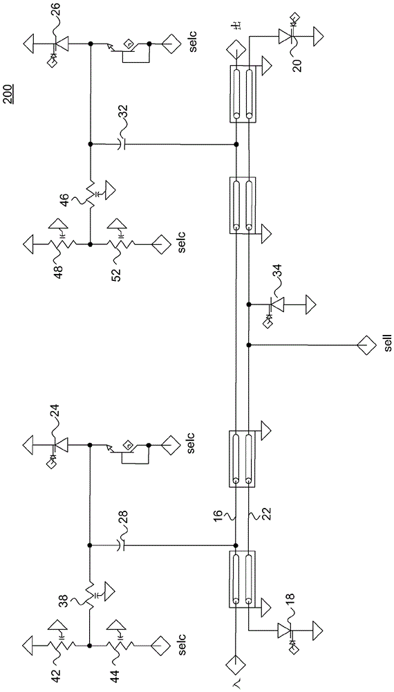
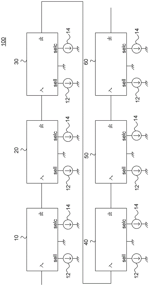
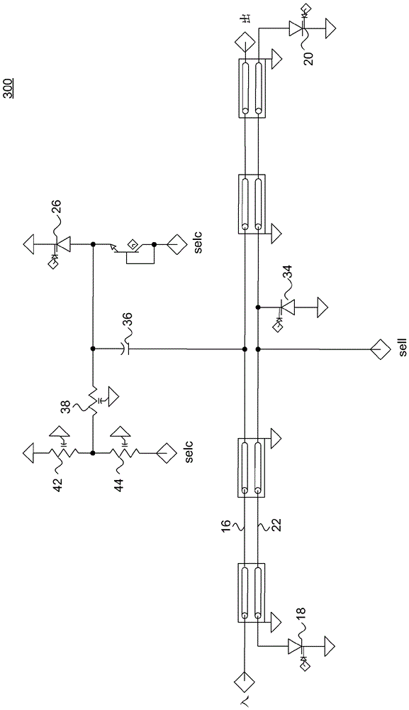
[0015] figure 1 shows a lumped element transmission line built using capacitors, switches, and coupled transmission line segments, while figure 2 An example segment is illustrated.

[0016] figure 1 A six-segment electronically variable analog delay line 100 is shown having four equal delay segments 10 with a switchable delay of nominally 4 ps (in short delay mode) or nominally 6.4 ps (in long delay mode). 20, 30 and 40, followed by two additional segments 50 and 60 of approximately half and quarter lengths. For example, segment 50 could be 0.5 times the length of four equal delay segments (resulting in a nominal 2ps delay in short delay mode and a nominal 3.2ps delay in long delay mode) while segment 60 is four equal delay segments 0.25 times the length of (resulting in a nominal 1ps delay in...


PUM


Abstract

An electronically variable analog delay line including at least one segment with an electronically variable inductance. The at least one segment includes a signal path, a ground return path, and a plurality of switches configured to vary the inductance of the segment.

Description

technical field [0001] The present disclosure relates to an electronically variable analog delay line having a signal path and a ground return path to electronically vary the inductance of the electronically variable analog delay line in a short delay mode and a long delay mode. Background technique [0002] Differential input probes are typically used to acquire nominally differential signals, such as on a high-speed serial data bus, from a device under test (DUT) using a single test and measurement instrument channel. TriMode TM The probes have the added ability to acquire common mode signals or either side of a differential pair signal as a single-ended signal. [0003] An ideal differential signal consists of two complementary signals sent on two separate wires. Any skew or difference in delay between the two sides of the wiring in the DUT to the test and measurement instrument and / or within the test and measurement instrument itself causes mode conversion of the diffe...

Claims


Application Information

Patent Timeline
Patent Type & Authority Applications(China)
IPC IPC(8): H03K5/14
CPCH03K5/14H01P9/00H03H7/185H03H7/345H03K5/133H03K2005/00045H03H11/265
Inventor D.G.克尼里姆
Owner TEKTRONIX INC
Why Eureka
Try Eureka