Rotary vamp cutting device for shoemaking

A cutting device and a rotating technology, which can be used in footwear, applications, heel pads, etc., can solve the problems of inflexible cutting, waste of resources, and weak practicability, and achieve good shredding effect, improved utilization efficiency, and practical strong effect

Active Publication Date: 2017-01-04
温州市耐锐鞋业有限公司
View PDF4 Cites 0 Cited by
  • Summary
  • Abstract
  • Description
  • Claims
  • Application Information

AI Technical Summary

Problems solved by technology

[0008] In order to overcome the disadvantages of inflexible cutting, waste of resources and weak practicability in the existing shoe upper cutting device, the technical problem t

Method used


Image

  • Rotary vamp cutting device for shoemaking
  • Rotary vamp cutting device for shoemaking
  • Rotary vamp cutting device for shoemaking

Examples


Example Embodiment

[0030] Example 1

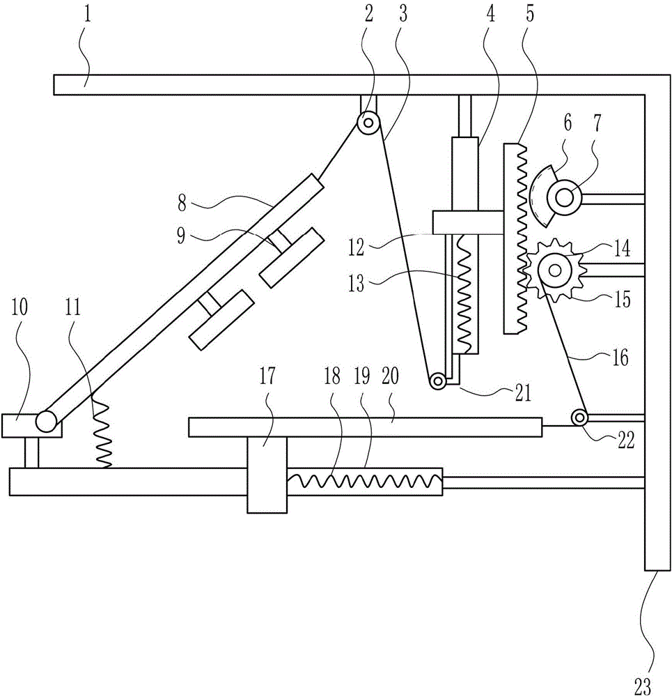
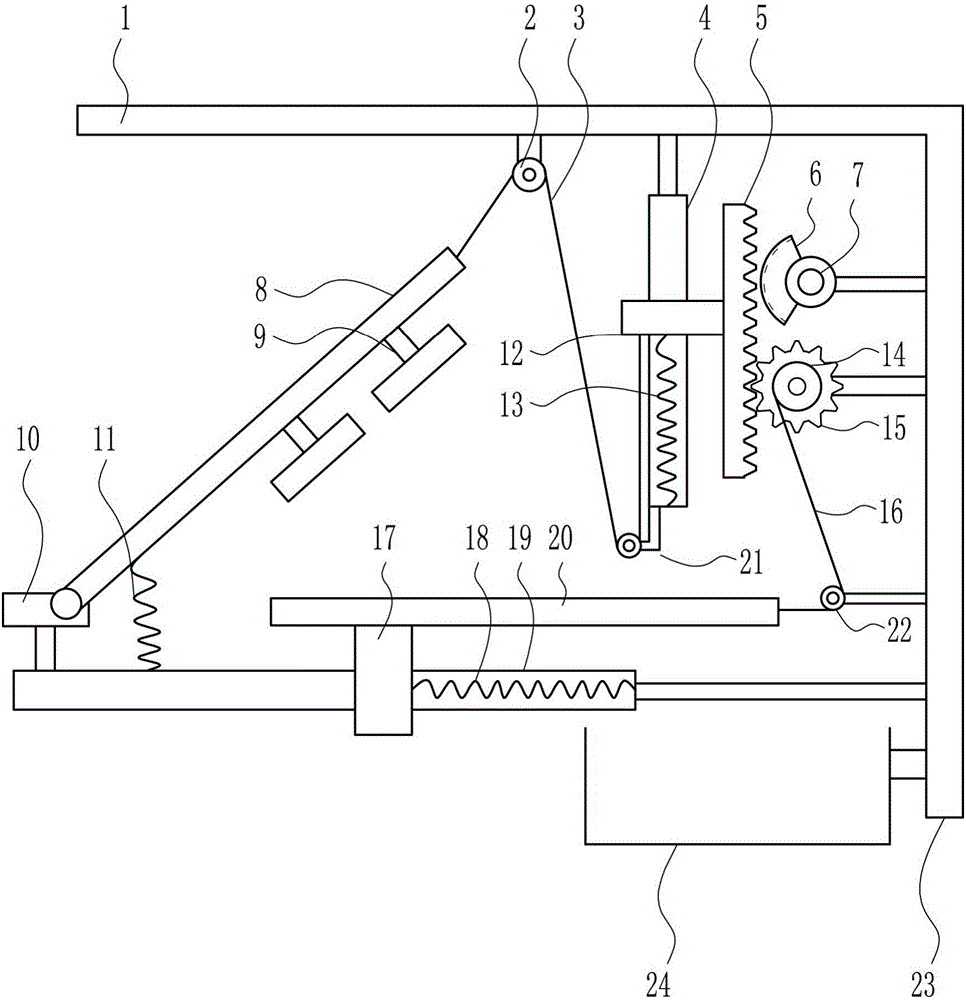
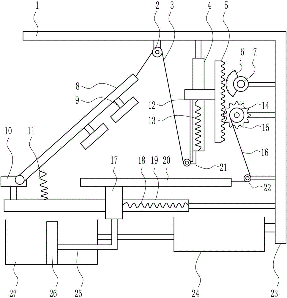
[0031] A shoe upper rotary cutting device for making shoes, such as Figure 1-4 As shown, it includes a top plate 1, a first roller 2, a first pull wire 3, a first slide rail 4, a rack 5, a sector gear 6, a reduction motor 7, a rotating plate 8, a knife die 9, a fixed block 10, and a third Spring 11, first slide block 12, first spring 13, reel 14, bull gear 15, second backguy 16, second slide block 17, second spring 18, second slide rail 19, place plate 20, the first The second roller 21, the third roller 22 and the right frame 23; the right frame 23 is connected to the bottom right side of the top plate 1, and the top plate 1 is connected with the first roller 2 and the first slide rail 4 sequentially from left to right, and the first roller 2 is wound There is a first stay wire 3, a first slide block 12 is arranged on the first slide rail 4, a rack 5 is connected to the right side of the first slide block 12, and a rack 5 is connected between the bottom o...


PUM


Abstract

The present invention relates to a vamp cutting apparatus, and in particular to a rotary vamp cutting device for shoemaking. The technical problem to be solved by the present invention is to provide a rotary vamp cutting device for shoemaking, which is flexible in cutting and capable of recycling resources and practically strong. In order to solve the above-mentioned technical problems, the present invention provides a rotary vamp cutting device for shoemaking. The rotary vamp cutting device comprises a top plate, a first roller, a first cable, a first rail, a rack, a sector gear, a gear motor, a rotary plate, a cutter mold, a fixed block, a third spring, a first slider, a first spring, a reel, a main gear, a second cable, a second slider, a second spring, a second slide, a plate, a second roller, a third roller and a right bracket. The rotary vamp cutting device achieves the effect of cutting flexibility, recyclable resources and practical effect. When the vamp cutting work is to be carried out, the device can improve the utilization efficiency of resources and save a lot of working time.

Description


Claims


Application Information

Patent Timeline
Owner 温州市耐锐鞋业有限公司
Why Eureka
Try Eureka