
Separate type injection deashing device

A soot cleaning device and separate technology, which is applied in the field of separate blowing soot cleaning devices, can solve the problems of heavy maintenance workload and high investment costs, achieve the effects of saving investment and operation and maintenance costs, and improving economic and social benefits

Inactive Publication Date: 2017-01-04
WUXI XUELANG ENVIRONMENTAL TECH CO LTD
View PDF7 Cites 1 Cited by
  • Summary
  • Abstract
  • Description
  • Claims
  • Application Information

AI Technical Summary

Problems solved by technology

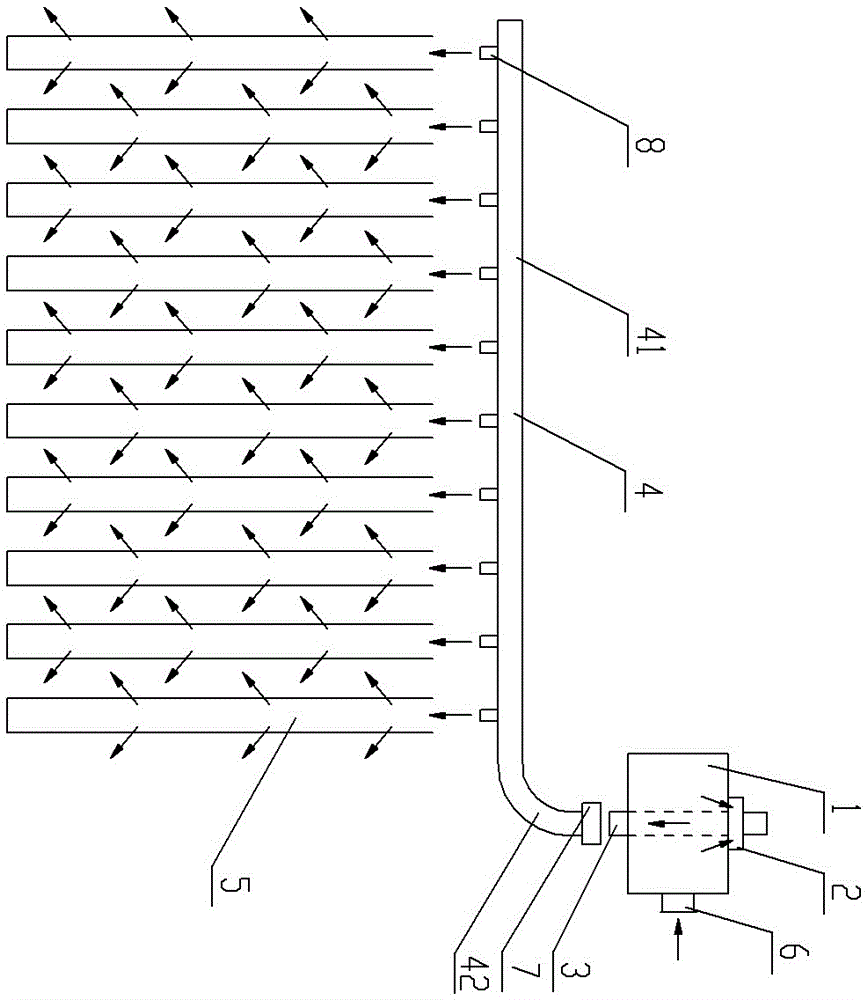
[0002] Most of the existing pulse bag dust collectors use pipe-type blowing dust cleaning devices, which are mainly composed of air bags, pulse valves, blowing pipes, filter bags, etc. The air bags and pulse valves are fixed, and one air bag is connected to multiple pulse valves. A pulse valve is connected to a blowing pipe, and a blowing pipe sprays a row of multiple filter bags. When the filter bags need to be cleaned, a pulse valve is opened first, and the compressed air in the air bag enters the blowing pipe, and then passes through the pipe wall. Multiple nozzles on the lower side spray out at the same time, and spray into the corresponding filter bags respectively. However, because the pulse bag filter has a large number of filter bags, the number of filter bag rows is tens or even hundreds, and the number of corresponding pulse valves and air bags is also large. Quite a lot, high investment cost, heavy maintenance workload

Method used


Image

  • Separate type injection deashing device
  • Separate type injection deashing device

Examples


Embodiment Construction

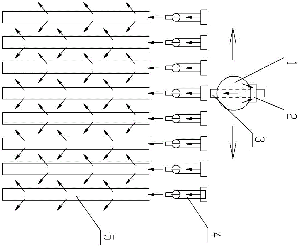
[0010] See figure 1 , figure 2 , the present invention includes an air bag 1, a pulse valve 2, a short connecting pipe 3, a blowing pipe 4, and a filter bag 5. The pulse valve 2 adopts a submerged pulse valve, and the compressed air source is connected to the air bag inlet 6. On the air bag 1 There is an air outlet of the air bag, and it is located on the upper part of the air bag 1. The valve seat of the pulse valve 2 is embedded in the air outlet of the air bag. The air inlet of the pulse valve 2 is connected to the air outlet of the air bag. The air outlet of the pulse valve 2 is set on Inside the air bag 1, one end of the connecting short pipe 3 passes through the lower bottom surface of the air bag 1 and communicates with the air outlet of the pulse valve 2 inside the air bag 1, and the other end of the connecting short pipe 3 and the corresponding blowing pipe 4 below pass through the sealer 7 detachable connection, the outlet of the nozzle 8 on the lower side of the b...


PUM


Abstract

The invention provides a separate type injection deashing device which can reduce quantity of pulse valves and air pockets, reduce investment cost and reduce maintenance workload. The separate type injection deashing device comprises an air pocket, a pulse valve, an injection pipe and a filter bag as well as a junction pipe, wherein an air pocket air inlet is formed in the air pocket, a compressed air source is connected with the air pocket air inlet, an air pocket air outlet is formed in the air pocket and arranged at the upper part of the air pocket, a valve seat of the pulse valve is embedded into the air pocket air outlet, an air inlet of the pulse valve is connected with the air pocket air outlet, an air outlet of the pulse valve is formed inside the air pocket, one end of the junction pipe penetrates through the air pocket to be communicated with the air outlet of the pulse valve inside the air pocket, the other end of the junction pipe is detachably connected with the corresponding injection pipe arranged below the junction pipe, and a nozzle outlet in the lower side of the injection pipe faces an opening of the filter bag.

Description

technical field [0001] The invention relates to the technical field of dust removal in the energy saving and environmental protection industry, in particular to a separate blowing and dust removal device. Background technique [0002] Most of the existing pulse bag dust collectors use pipe-type blowing dust cleaning devices, which are mainly composed of air bags, pulse valves, blowing pipes, filter bags, etc. The air bags and pulse valves are fixed, and one air bag is connected to multiple pulse valves. A pulse valve is connected to a blowing pipe, and a blowing pipe sprays a row of multiple filter bags. When the filter bags need to be cleaned, a pulse valve is opened first, and the compressed air in the air bag enters the blowing pipe, and then passes through the pipe wall. Multiple nozzles on the lower side spray out at the same time, and spray into the corresponding filter bags respectively. However, because the pulse bag filter has a large number of filter bags, the numb...

Claims


Application Information

Patent Timeline
IPC IPC(8): B01D46/04
CPCB01D46/04
Inventor 尹华勤
Owner WUXI XUELANG ENVIRONMENTAL TECH CO LTD
Learn More