Piston reciprocating tank engine

An engine and tank technology, applied in the field of piston reciprocating tank engines, can solve the problems of occupying tank space and fixed investment costs, increasing tank fixed investment and complexity, occupying tank space and carrying capacity, etc., to reduce complexity and fixed investment. The effect of cost, simple structure and low cost

Active Publication Date: 2019-02-01
肖光宇
View PDF24 Cites 0 Cited by
  • Summary
  • Abstract
  • Description
  • Claims
  • Application Information

AI Technical Summary

Problems solved by technology

[0002] Most of the existing tank power units use V-type engines. The main reason is that when the number of engine cylinders is increased, compared with L-type engines, the fuselage is short, easy to arrange, and can also meet the power requirements of tanks, but the cost is expensive , complex structure, difficult maintenance and repair, and poor stability; since there is only one calibrated speed, it is difficult to take into account that the tank can work at a safe, stable and reliable maximum power at both low and high speeds, and a deceleration or transmission device must be set. , increasing the fixed investment and complexity of the tank, while also taking up valuable space and carrying capacity inside the tank
[0003] Especially when a certain cylinder of the engine fails or is damaged, the entire engine will stop working, causing the tank to be paralyzed. In addition, the engine is difficult to start and requires a relatively high-power starting device, which also takes up valuable space and fixed parts of the tank. investment cost

Method used


Image

  • Piston reciprocating tank engine
  • Piston reciprocating tank engine
  • Piston reciprocating tank engine

Examples


Embodiment Construction

[0043] The present invention will be further described below in conjunction with the accompanying drawings.

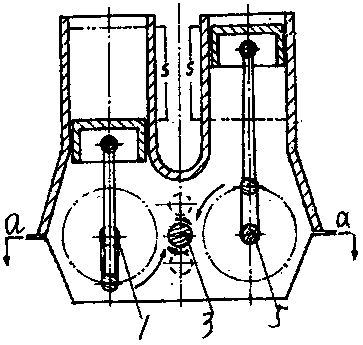
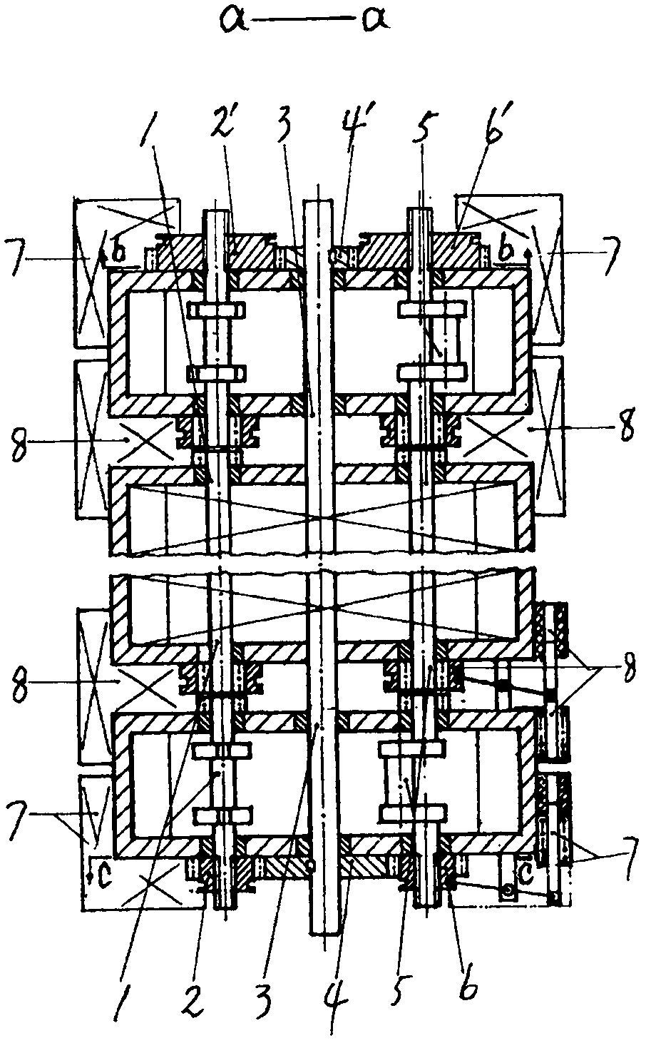
[0044] Such as figure 1 Shown: The same L-shaped two cylinders are connected vertically and parallelly to form a U-shaped double cylinder, combined figure 2 It shows that multiple rows of U-shaped twin cylinders are connected in series to form an engine composed of multiple rows of U-shaped twin cylinders.

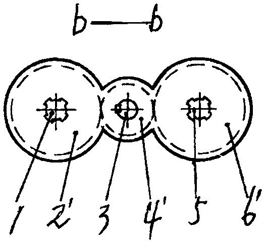
[0045] figure 1 to combine figure 2 Shown: the power transmission system of the engine is composed of left and right crankshafts (1, 5), output shaft (3), left and right crankshaft gears (2, 6), and output shaft gears (4); the output shafts are arranged on the left and right On the vertical line in the middle of the line connecting the crankshaft centers, its up and down positions can be above or below the line connecting the centers of the two crankshafts, such as figure 1 The dotted line in the small circle shows that it can also be made on the connecting lin...


PUM


Abstract

The invention discloses a piston reciprocating tank engine. The piston reciprocating tank engine is formed by connecting a plurality of rows of U-shaped cylinders in series, wherein each U-shaped cylinder is formed by connecting two L-shaped cylinders perpendicularly and in parallel. The engine rated speed output by an output shaft (3) to the outside can be changed by changing the reference diameter ratio of crank gears (2 and 6) of each gear set to an output shaft gear (4). Clutch mechanisms (7) are arranged on the outer sides of the crank gears of the front and back gear sets, and clutch mechanisms (8) are arranged between axially adjacent crank sections, and a working cylinder can be stopped or linked according to the requirement of a working condition. Therefore, the advantages that the L-shaped engine cylinders and cranks are simple in structure, easy to manufacture and maintain, low in manufacturing cost, good in stability performance and high in thermal efficiency are achieved,and the advantages that a V-shaped engine body is short and convenient to arrange are also achieved; particularly, the engine rated speed, the number of the cylinders and the power can be directly adjusted, a deceleration or a speed change gear is omitted, and starting is convenient; and when a certain working cylinder breaks down or is damaged, the working cylinder can be disengaged and stops running while the engine can still continue to operate.

Description

technical field [0001] The invention belongs to the field of internal combustion engines, and in particular relates to a piston reciprocating tank engine. Background technique [0002] Most of the existing tank power units use V-type engines. The main reason is that when the number of engine cylinders is increased, compared with L-type engines, the fuselage is short, easy to arrange, and can also meet the power requirements of tanks, but the cost is expensive , complex structure, difficult maintenance and repair, and poor stability; since there is only one calibrated speed, it is difficult to take into account that the tank can work at a safe, stable and reliable maximum power at both low and high speeds, and a deceleration or transmission device must be set. , which increases the fixed investment and complexity of the tank, and also takes up valuable space and carrying capacity inside the tank. [0003] Especially when a certain cylinder of the engine fails or is damaged, ...

Claims


Application Information

Patent Timeline
Patent Type & Authority Applications(China)
IPC IPC(8): F02B75/32
CPCF02B75/32Y02T10/12
Inventor 肖光宇
Owner 肖光宇
Why Eureka
Try Eureka