

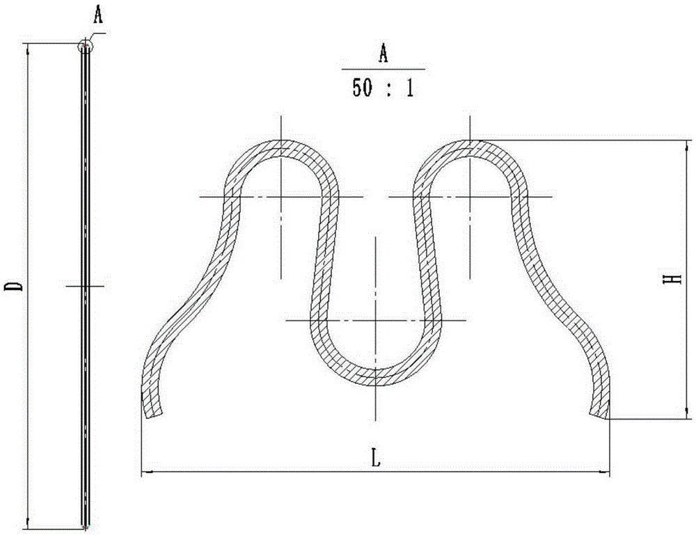
Single-pass integral molding device for M-shaped metal sealing ring
A technology of integral molding and sealing ring, which is applied in the field of molding molds, can solve the problems of adverse effects on the surface quality and forming accuracy of thin-walled parts, unfavorable control of cost and processing cycle, and difficult precise control of the molding process, so as to reduce molding defects possible occurrence, compact structure, and low cost
- Summary
- Abstract
- Description
- Claims
- Application Information
AI Technical Summary
Problems solved by technology
Method used
Image

Examples
Embodiment Construction
[0049] The technical solution of the present invention will be further described below in conjunction with the accompanying drawings.
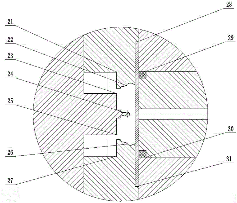
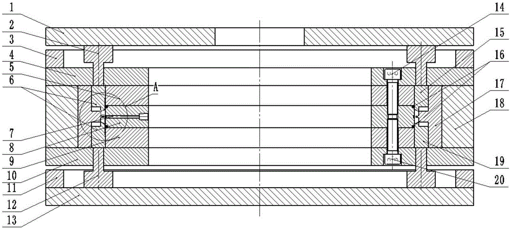
[0050] A single-pass overall molding device for an "M"-shaped metal sealing ring, such as Figure 2-5 As shown, it is characterized in that it includes: a bottom plate 13, and the bottom plate 13 is sequentially composed of a ring-shaped structure and a consistent axis of the pressing plate 1, the upper feeding briquetting block 2, the upper fixing plate 4, the upper sealing briquetting block 5, Liquid chamber module 8, lower sealing briquetting block 9, lower fixing plate 10, lower feeding briquetting block 12;
[0051] Among them, the outer ring wall surfaces of the upper sealing briquetting block 5, the liquid chamber module 8, and the lower sealing briquetting block 9 are flush, and the outer ring wall faces the movable mold 6 and the center of the annular structure composed of two symmetrical half molds. Die 17, annular strengthening col...
PUM
| Property | Measurement | Unit |
|---|---|---|
| yield strength | aaaaa | aaaaa |
Abstract
Description
Claims
Application Information