A method for forming a vacuum pump intake casing

A molding method and air intake cover technology, applied to casting molding equipment, molds, cores, etc., can solve the problems of increasing the production cost and efficiency of the intake cover, poor cooling effect of the intake cover, and limited heat dissipation area of ​​the cooling plate and other issues, to achieve the effect of convenient implementation, low cost, and prevention of melt-through

Active Publication Date: 2018-01-23
埃地沃兹
View PDF7 Cites 0 Cited by
  • Summary
  • Abstract
  • Description
  • Claims
  • Application Information

AI Technical Summary

Problems solved by technology

[0005] 1. The heat dissipation area formed by the cooling plate is limited, resulting in poor cooling effect of the air intake casing;
[0006] 2. It is necessary to further install the cooling plate, so there is one more production process, thereby increasing the production cost and efficiency of the air intake cover

Method used


Image

  • A method for forming a vacuum pump intake casing
  • A method for forming a vacuum pump intake casing

Examples


Embodiment Construction

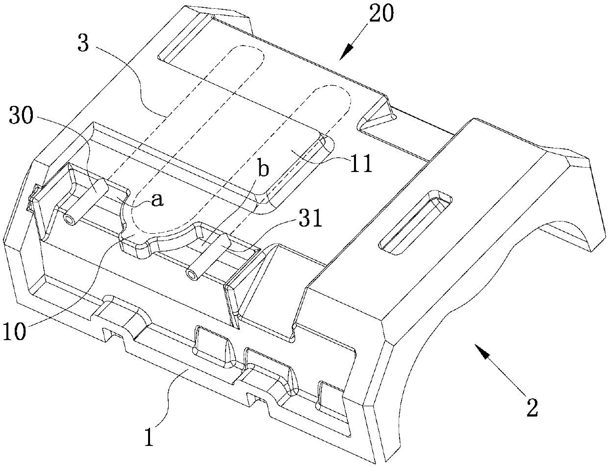
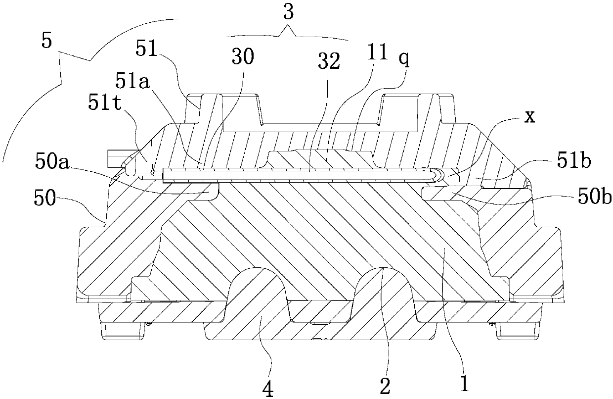
[0030] Such as figure 1 with figure 2 As shown, the intake casing of the vacuum pump of this embodiment includes a casing 1, a cavity on the casing 1 forming a space for the rotor to rotate, a condensing coil 3 arranged inside the casing 1, wherein the casing 1 It is formed by integral casting and fusion with the condensing coil 3. The condensing coil 3 is horizontally arranged above the cavity 2 and the formed cooling area covers the space of the cavity occupied by the rotor.

[0031] In this example, the molding die of the air intake cover includes a lower sand core 4 that forms the cavity 2 and an upper sand core 5 that forms the outer contour of the shell 1. The upper sand core 5 includes the lower sand core 4 which is attached to and used The first sand core 50 on which the condensing coil 3 is erected, and the second sand core 51 pressed on the first sand core 50 and the condensing coil 3.

[0032] The condensing coil 3 includes a tube body 32 fused in the shell 1, a medium...


PUM


Abstract

The invention relates to a molding method of an air inlet cover shell of a vacuum pump. The method comprises the following specific operation steps: (1) positioning a condensation coiled pipe in a mold cavity for forming a shell body by laminating a first sand core and a second sand core; (2) charging loose sand into the condensation coiled pipe and blocking hole parts of a medium inlet pipe and a medium outlet pipe of the condensation coiled pipe through end sockets; (3) putting a molding mold into a sand mold and leading molten iron into the mold cavity; covering a pipe body of the condensation coiled pipe through the molten iron and fusing; exhausting generated air through a pre-set air hole. By positioning the condensation coiled pipe through the first sand core and the second sand core, the pipe body is partially fused in the shell body and is integrally poured; the production efficiency of the air inlet cover shell is improved; meanwhile, the loose sand is charged into the condensation coiled pipe, so that the condensation coiled pipe is effectively prevented from being melted in a high-temprature fusing process; furthermore, the method is simple to operate, convenient to implement and low in cost.

Description

Technical field [0001] The utility model belongs to the field of mechanical casting, and in particular relates to a method for forming an air inlet cover of a vacuum pump. Background technique [0002] At present, the molding die of the vacuum pump air inlet cover is generally formed by casting. The air inlet cover mainly includes a shell and a cavity on the shell forming a space for the rotor to rotate. The cavity is along the length of the shell. Extended settings. [0003] However, in actual use, the temperature generated by the high-speed rotation of the rotor is relatively high. If the heat is not released in time, it is easy to cause safety accidents due to overheating of the vacuum pump. Therefore, further improvements are made to the air intake cover. A cooling plate is added to the body to dissipate heat from the air intake cover. [0004] Obviously, it has the following defects: [0005] 1. The heat dissipation area formed by the cooling plate is limited, resulting in poor...

Claims


Application Information

Patent Timeline
Patent Type & Authority Patents(China)
IPC IPC(8): B22C9/24B22C9/02
CPCB22C9/02B22C9/24
Inventor 王凯郭鹏飞
Owner 埃地沃兹
Why Eureka
Try Eureka