Magnetic mud separator
A technology of separator and magnetic mud, which is applied in the field of cooling liquid purification, can solve the problems of low quick recording of fine purification, and achieve the effect of high work efficiency and convenient operation
- Summary
- Abstract
- Description
- Claims
- Application Information
AI Technical Summary
Problems solved by technology
Method used
Image

Examples
Embodiment Construction
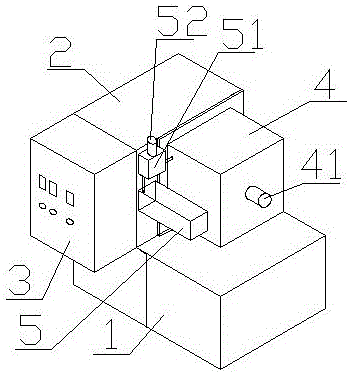
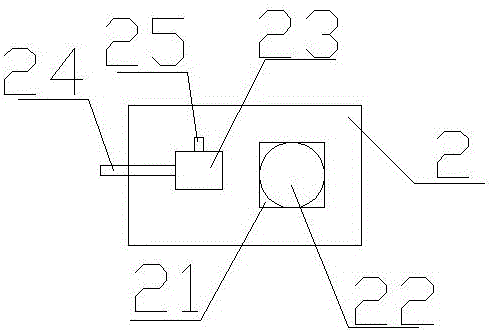
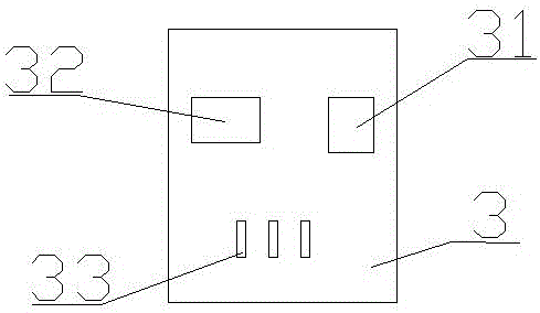
[0015] Such as Figure 1-Figure 4 As shown, the present invention discloses a magnetic mud separator, comprising: base 1, motorized box 2, control box 3, separation box 4, air pump 5, motor bracket 21, motor 22, liquid pump 23, water inlet pipe 24, guide Flow pipe 25, transformer 31, intelligent processor 32, switch 33, mud outlet 41, central shaft 42, spiral blade 43, spiral pipe 44, water outlet 45, airflow controller 51, air pressure gauge 52, described motorized box 2 is fixed on the upper end of the bracket 1 by screws, the control box 3 is fixed on the side of the motorized box 2 by screws, the separation box 4 is fixed on the back of the motorized box 3 by screws, and the air pump 5 is fixed on the motorized box by screws On the box 2, the motor bracket 21 is fixed in the motor box 2 by welding, the motor 22 is fixed on the motor bracket 21, and the liquid pump 23 is fixed in the motor box 2 by screws. The water pipe 24 is fixed on the liquid pump 23 by welding, the gu...
PUM
 Abstract
Description
Claims
Application Information