
Automatic calibration equipment for light intensity of DLP (Digital Light Processing) printing equipment projector and calibration method

A technology for automatic calibration and printing equipment, applied in the field of 3D printing, can solve the problems of the printing accuracy and printing efficiency of rapid prototyping equipment, uneven light intensity distribution in the projection area, large light intensity errors in the image, etc., to achieve high guidance accuracy and stability. High performance, stable focus and moving effects

Active Publication Date: 2017-01-04
SUZHOU BC TECH
View PDF4 Cites 16 Cited by
  • Summary
  • Abstract
  • Description
  • Claims
  • Application Information

AI Technical Summary

Problems solved by technology

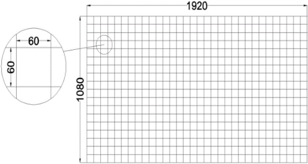
However, due to the unavoidable precision problems of the optical components in the projector, there is a large light intensity error in the projected image, and the uneven light intensity distribution in the projection area has a great impact on the printing accuracy and printing efficiency of the rapid prototyping equipment. influences
At this stage, there is no automatic calibration equipment for DLP projectors, and the traditional calibration method is time-consuming and laborious

Method used


Image

  • Automatic calibration equipment for light intensity of DLP (Digital Light Processing) printing equipment projector and calibration method
  • Automatic calibration equipment for light intensity of DLP (Digital Light Processing) printing equipment projector and calibration method
  • Automatic calibration equipment for light intensity of DLP (Digital Light Processing) printing equipment projector and calibration method

Examples


Embodiment Construction

[0031] The following will clearly and completely describe the technical solutions in the embodiments of the present invention with reference to the accompanying drawings in the embodiments of the present invention. Obviously, the described embodiments are only some, not all, embodiments of the present invention. Based on the embodiments of the present invention, all other embodiments obtained by persons of ordinary skill in the art without creative efforts fall within the protection scope of the present invention.

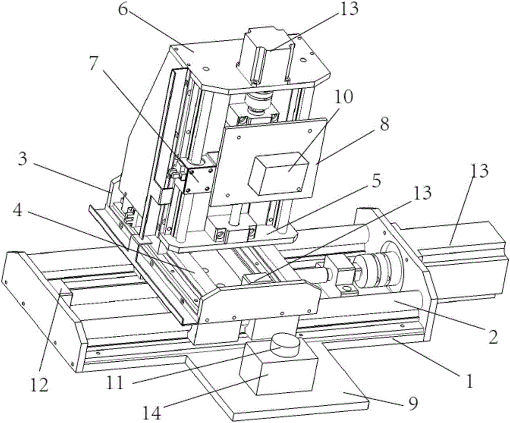
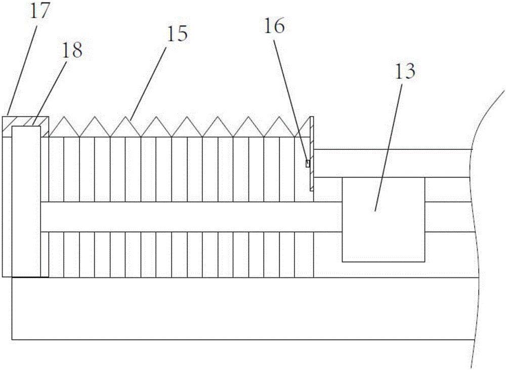
[0032] refer to Figure 1 to Figure 4 As shown, a DLP printing equipment projector light intensity automatic calibration equipment, including a base 1, two first cylindrical linear guides 2 moving along the X-axis direction are arranged in parallel on the base, and two first cylindrical linear guides are provided with The first slide platform 3 that slides along the X-axis direction, two second cylindrical linear guides 4 that move along the Y-axis direction are ar...


PUM


Abstract

The invention discloses automatic calibration equipment for the light intensity of a DLP (Digital Light Processing) printing equipment projector. The automatic calibration equipment comprises a base; the base is provided with a first cylindrical linear guide rail which moves along the X-axis direction, a first sliding platform, a second cylindrical linear guide rail which moves along the Y-axis direction, a second sliding platform, a mounting platform, a third cylindrical linear guide rail which moves along the Z-axis direction and a third sliding platform in sequence from bottom to top; an extending platform is arranged at a side edge of the base in front of the third sliding platform; the third sliding platform and the extending platform are provided with a projector and a light intensity sensor respectively; the projector and the light intensity sensor are connected with a system control board; a calibration method comprises the following steps: step (1) focusing and adjusting; step (2) determining calibration reference light intensity; step (3) collecting compensation mask gray level numerical value of the projector; step (4) generating a compensation mask; step (5) carrying out calibration. The automatic calibration equipment provided by the invention is reasonable in design, compact in structure, convenient to operate and good in stability and can effectively obtain the light intensity of the projector.

Description

technical field [0001] The invention relates to the technical field of 3D printing, in particular to a DLP printing equipment projector light intensity automatic calibration equipment and a calibration method. Background technique [0002] 3D printing technology (also known as rapid prototyping) is a new manufacturing technology that emerged in the late 1980s. It uses modern means such as computers, lasers, precision transmission, and numerical control to realize rapid manufacturing of workpieces through layer-by-layer stacking of raw materials. This emerging manufacturing technology integrates computer-aided design and computer-aided manufacturing. First, the three-dimensional solid model drawn in advance is layered according to a certain thickness, and then the solidification and stacking of raw materials is completed through the cooperation of the motion control system and the optical system. The molding entity is not limited by the shape, and has the advantages of fast m...

Claims


Application Information

Patent Timeline
IPC IPC(8): B29C67/00B33Y30/00B33Y50/02
CPCB33Y30/00B33Y50/02
Inventor 陈号邱志惠黄祺王智郭池戴晨雨
Owner SUZHOU BC TECH
Learn More