Traction connecting rod mechanism for railway vehicles and frame protection method

A rail vehicle and traction link technology, applied in the direction of railway vehicles, bogies, motor vehicles, etc., can solve the problems of inability to protect the frame, inability to buffer the track and the bogie, inability to protect the bogie, etc., so that the vehicle can turn easily and increase The effect of rotational force

Inactive Publication Date: 2017-01-04
ZHUZHOU TIMES NEW MATERIALS TECH
View PDF8 Cites 9 Cited by
  • Summary
  • Abstract
  • Description
  • Claims
  • Application Information

AI Technical Summary

Problems solved by technology

[0006] Although the patent with the application number CN201510915678.7 is also a traction linkage mechanism for rail transit monorail vehicles, there is no oil pressure spring assembly installed between the anti-roll bar components, and the traction linkage mechanism and the bogie will not be connected when the vehicle is turn

Method used


Image

  • Traction connecting rod mechanism for railway vehicles and frame protection method
  • Traction connecting rod mechanism for railway vehicles and frame protection method
  • Traction connecting rod mechanism for railway vehicles and frame protection method

Examples


Embodiment 1

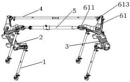
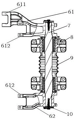
[0030] Such as figure 1 and figure 2 As shown, the anti-roll bar assembly includes a left anti-roll bar assembly 2 and a right anti-roll bar assembly 3 , and the structures of the left anti-roll bar assembly 2 and the right anti-roll bar assembly 3 are distributed symmetrically. The transmission shaft 7 is arranged in the middle of the anti-roll bar assembly, and the transmission arm includes an upper transmission arm 61 and a lower transmission arm 62. The upper transmission arm 61 is located at the upper end of the transmission shaft 7, and the lower transmission arm 62 is located at the lower end of the transmission shaft. The transmission arm is fixedly matched with the transmission shaft 7, and is positioned with the shaft shoulder 10. The transverse link assembly 4 and the hydraulic spring assembly 5 are installed between the upper transmission arms 61 of the two sets of anti-roll bar assemblies, and the drawbar assembly 1 is installed in the drawbar assembly support 6...


PUM


Abstract

The invention discloses a traction connecting rod mechanism for railway vehicles. A traction rod assembly, a power-assisted steering device and an overload protection device are arranged on an anti-roll bar assembly; one end of the traction rod assembly is connected with the anti-roll bar assembly; two ends of the power-assisted steering device and the overload protection device are respectively connected with one group of anti-roll bar assemblies. An oil pressure spring in an oil pressure spring assembly mounted between the two groups of anti-roll bar assemblies always provides tension outwards, and the turning power of the traction connecting rod mechanism can be increased, so that the vehicles are easy to turn; and moreover, the oil pressure spring is an elastic part and is capable of buffering acting force of the rails on a bogie while turning, so that the bogie can be well protected. A transverse casing in a transverse connecting rod assembly mounted between two groups of anti-roll bar assemblies can be automatically broken when a vehicle load is extremely high, so that the frame is prevented from being damaged.

Description

technical field [0001] The invention relates to a traction connection mechanism on a rail vehicle, in particular to a traction linkage mechanism and a frame protection method for a rail transit monorail vehicle. Background technique [0002] Urban rail transit has gradually become the first choice for people to travel due to its obvious advantages of convenience and speed, but its disadvantages are also obvious, that is, large investment, difficulty in line selection and construction, which promotes the popularity of monorail vehicles. Monorail vehicles have the advantages of small turning radius, strong climbing ability, and low operating noise. To a certain extent, they overcome the difficulties of line selection and construction. Its application is becoming more and more extensive, and it has gradually become the mainstream urban rail transit mode. [0003] In rail vehicles bogies are used to support the car body and are used in the final assembly of the vehicle. The str...

Claims


Application Information

Patent Timeline
IPC IPC(8): B61F5/02B61F5/24B61B13/06
CPCB61F5/02B61B13/06B61F5/245
Inventor 倪世锋刘文松杜方孟邹敏佳王亚平聂清明
Owner ZHUZHOU TIMES NEW MATERIALS TECH
Why Eureka
Try Eureka