
Locking device for foldable draw gear, foldable draw gear and locking method of foldable draw gear

A locking device and folding technology, which is applied in the field of locking devices of folding couplers, can solve the problem that the locking device takes up a lot of space, and achieve the effect of reducing the occupied space

Active Publication Date: 2017-01-04
CRRC QINGDAO SIFANG ROLLING STOCK RES INST
View PDF4 Cites 11 Cited by
  • Summary
  • Abstract
  • Description
  • Claims
  • Application Information

AI Technical Summary

Problems solved by technology

[0007] In order to solve the problem that the locking device occupies too much space in the prior art, the present invention provides a locking device for a folding coupler, a folding coupler and a locking method thereof

Method used

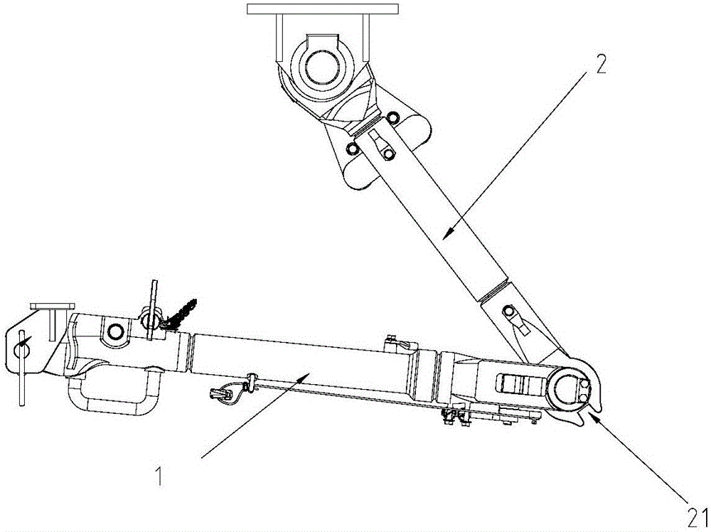
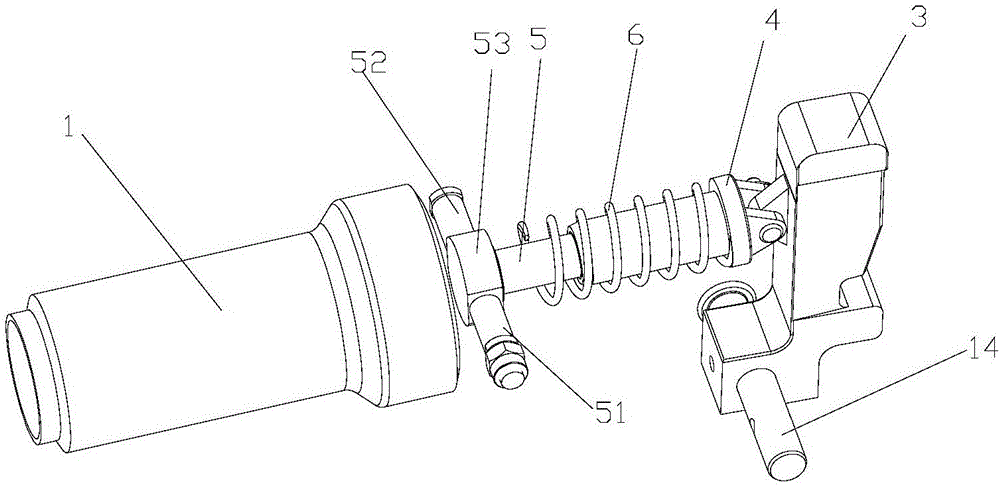

Image

  • Locking device for foldable draw gear, foldable draw gear and locking method of foldable draw gear
  • Locking device for foldable draw gear, foldable draw gear and locking method of foldable draw gear
  • Locking device for foldable draw gear, foldable draw gear and locking method of foldable draw gear

Examples


Embodiment

[0031] Example: such as figure 1 , figure 2 Shown, sovereign content plus effects.

[0032] In the description of the present invention, it should be noted that the length direction of the present invention is the horizontal direction of the straight state of the coupler; the terms "inner", "outer", "upper", "lower", "front", "rear ” and other indications of orientation or positional relationship are based on the attached figure 2 The positional relationship shown is only for the convenience of describing the present invention and simplifying the description, but does not indicate or imply that the referred device or element must have a specific orientation, be constructed and operated in a specific orientation, and therefore cannot be construed as limiting the present invention . In addition, the terms "first", "second", and "third" are used for descriptive purposes only, and should not be construed as indicating or implying relative importance.

[0033] see image 3 a...


PUM


Abstract

The invention provides a locking device for a foldable draw gear, the foldable draw gear and a locking method of the foldable draw gear. The locking device is used for locking a front pull rod and a rear pull rod of the foldable draw gear in a straightened state. The locking device comprises a locking check block. A spring sleeve is hinged to the end portion of the end, far away from the rear pull rod, of the locking check block, and the spring sleeve is in a tube shape with one end being closed and the other end being open. The closed end of the spring sleeve is hinged to the locking check block, a spring shaft is sleeved with the other end of the spring sleeve, a transversal limiting unit is arranged at the other end of the spring shaft in a hinged mode and fixed to the two sides of the front pull rod, and the spring shaft (5) can rotate around the transversal limiting unit. The spring shaft (5) and the spring sleeve (4) are sleeved with a spring (6) capable of keeping the locked state of the front pull rod and the rear pull rod. The locking device solves the problem that a locking device in the prior art occupies too much space.

Description

technical field [0001] The invention belongs to the field of connection between tram cars, in particular to a locking device for a folding coupler. Background technique [0002] The folding coupler of the tram is generally located under the train driver's cab, behind the opening and closing mechanism of the car end and the shroud. [0003] Such as figure 1 Shown is the schematic diagram of existing collapsible coupler. Such as figure 1 As shown, the foldable coupler includes a front pull rod 1 and a rear pull rod 2 that can rotate with each other. When the train is running normally, the coupler is in a folded state and is fixed under the car body by the hook head fixing device. At this moment, the U-shaped groove 21 of the rear tie rod 2 turns out to the outside of the front tie rod 1 . [0004] Such as figure 2 As shown, it is a schematic diagram of the straightening state of the existing collapsible coupler. Such as figure 2 As shown, when the train needs to be re...

Claims


Application Information

Patent Timeline
IPC IPC(8): B61G7/08
CPCB61G7/08
Inventor 赵海刘辉杨杰黄慧
Owner CRRC QINGDAO SIFANG ROLLING STOCK RES INST
Learn More