

Aircraft engine lifting device
A technology for aero-engines and lifting devices, applied in the direction of lifting devices, lifting frames, etc., can solve the problems of high labor intensity for operators, increase safety in production, and low work efficiency, achieve increased explosion-proof self-locking functions, reduce labor intensity, The effect of improving work efficiency
- Summary
- Abstract
- Description
- Claims
- Application Information
AI Technical Summary
Problems solved by technology
Method used
Image

Examples
Embodiment Construction
[0027] Below in conjunction with accompanying drawing and embodiment the present invention is described in further detail:
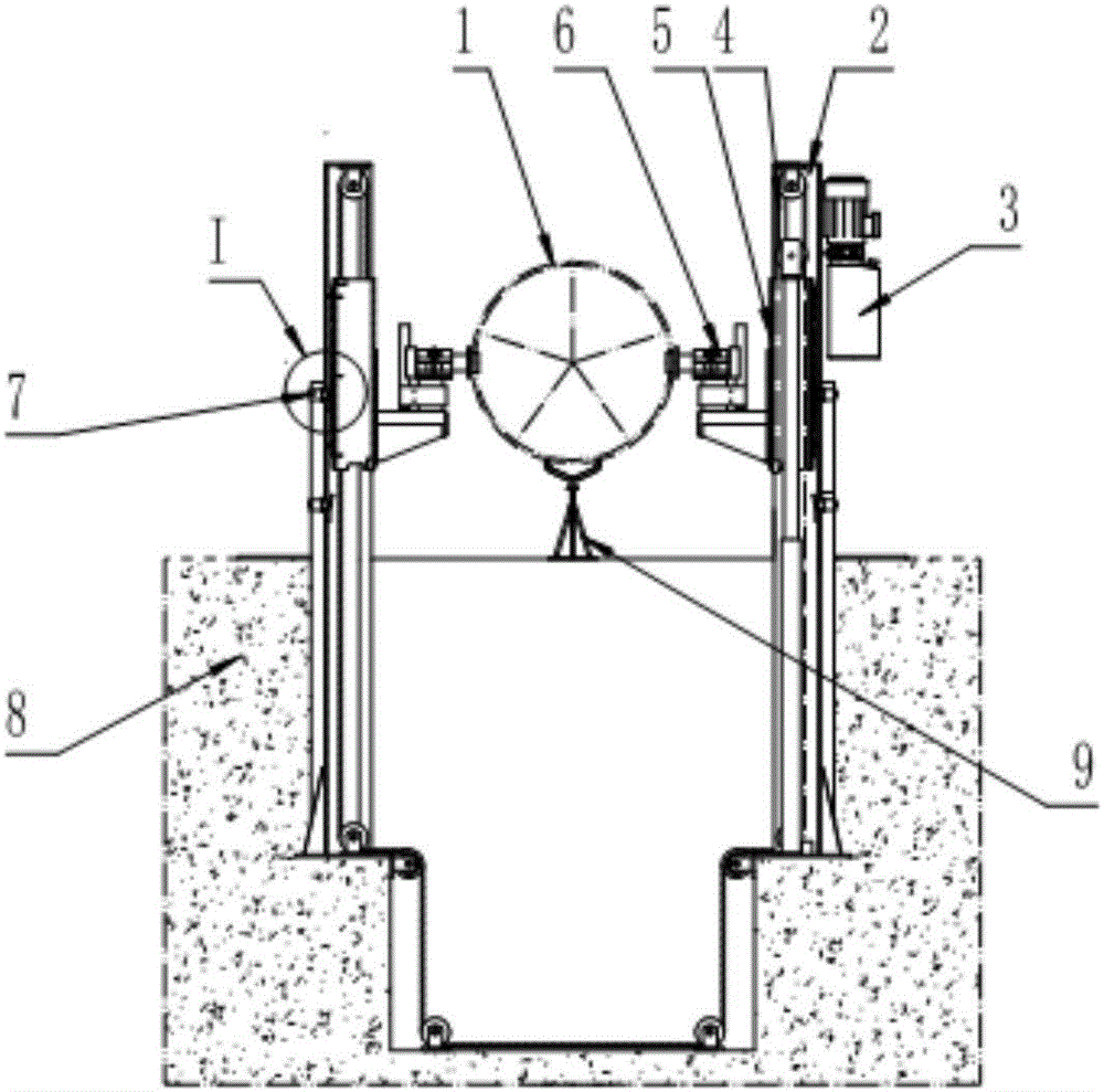
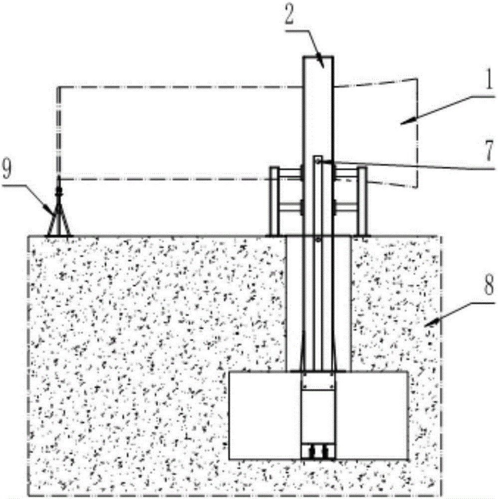
[0028] see figure 1 , figure 2 , Figure 7 , the aero-engine lifting device of the present invention is arranged on the engine assembly groove base 8, including a column 2, a sliding lifting body 5, a lifting drive mechanism 3, an engine support mechanism 6 and an auxiliary support mechanism 9; the column 2 is left and right The symmetrically arranged channel steel structure is equipped with a sliding lifting body 5 on the left column and the right column respectively; Install the engine support mechanism 6; the engine support mechanism 6 is provided with a support shaft 6-1, an axle seat 6-2 and a support assembly 6-3, and the support assembly 6-3 is fixed on the side wall of the sliding lifting body 5, The shaft seat 6-2 is installed on the bracket assembly 6-3, and the support shaft 6-1 is hingedly assembled with the shaft seat 6-2; the auxiliary ...
PUM
 Abstract
Description
Claims
Application Information