Rotary pipeline connecting system

A connection system and rotary joint technology, applied in the field of rotatable pipeline connection systems, can solve the problems of broken seals, easy fouling on the inner wall, and odor emission, and achieve the effects of preventing water leakage, flexible rotation, and avoiding odors.

Inactive Publication Date: 2017-01-04
WUHAN YANCHENG TECH CO LTD
View PDF5 Cites 2 Cited by
  • Summary
  • Abstract
  • Description
  • Claims
  • Application Information

AI Technical Summary

Problems solved by technology

[0002] For fixed sewer devices (for example: sinks, bathroom basins), sewer pipes generally use fixed drainage pipes, but now many sewer devices are movable. For such movable sewer devices, drainage pipes generally use plastic bellows or Plug-in telescopic tube; the inner wall of the plastic bellows is corrugated. After a long time, the inner wall is prone to fouling and emits odors, and because it is an active sewer device, the bellows will also move with the sewer device. The outer wall of the bellows Rubbing back and forth with the ground, the corrugated tube is easy to wear and tear; the expansion distance of the plug-in telescopic tube is large and it is easy to be damaged. At the same time, in order to ensure flexible expansion and contraction, the seal should not be too tight. Tightening and stretching is too laborious, and the axial friction between the inner wall of the pipe and the seal is likely to cause the seal to be cut or severely worn, and water will also leak

Method used


Image

  • Rotary pipeline connecting system
  • Rotary pipeline connecting system
  • Rotary pipeline connecting system

Examples


Embodiment 1

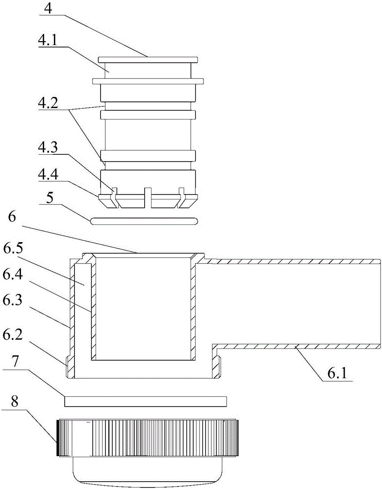
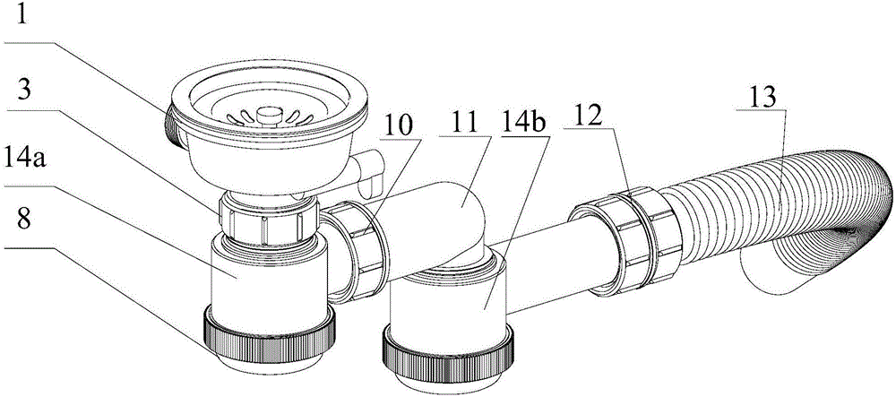
[0028] combine figure 1 and figure 2 As shown, a rotatable pipeline connection system includes two sets of rotary joint assemblies, the rotary joint assembly includes a water trap 6 and a rotatable direct pipe 4 sleeved in the water trap 6;

[0029] Wherein, the trap 6 includes a vertical pipe 6.3, a side pipe 6.1, a casing 6.4, a trap head 8, a casing 6.4 is arranged inside the vertical pipe 6.3, and the bottom of the casing 6.4 and the vertical pipe 6.3 correspond to the A "U"-shaped gap 6.5 is formed between the side walls. The upper end of the "U"-shaped gap 6.5 is closed, and the lower end is provided with a trap head 8 that is detachably connected. The "U"-shaped gap 6.5 communicates with the side pipe 6.1; The outer wall of the lower end of the vertical pipe 6.3 of the water trap 6 is provided with a screw thread 6.2 that cooperates with the water trap head 8, and the joint between the water trap head 8 and the water trap 6 is provided with a gasket 7.

[0030] Where...

Embodiment 2

[0034] Such as figure 1 As shown, a rotatable pipeline connection system includes a rotary joint assembly, and the rotary joint assembly includes a water trap 6 and a rotatable direct pipe 4 sleeved in the water trap 6;

[0035] Among them, the trap 6 includes a vertical pipe 6.3, a side pipe 6.1, a casing 6.4, and a trap head 8. The vertical pipe 6.3 is provided with a casing 6.4, and the bottom and side of the casing 6.4 correspond to the vertical pipe 6.3. A "U"-shaped gap 6.5 is formed between the walls, the upper end of the "U"-shaped gap 6.5 is closed, and the lower end is provided with a trap head 8 that is detachably connected, and the "U"-shaped gap 6.5 communicates with the side pipe 6.1; The outer wall of the lower end of the vertical pipe 6.3 of the water trap 6 is provided with a screw thread 6.2 cooperating with the water trap head 8, and a gasket 7 is provided at the connection between the water trap head 8 and the water trap 6.

[0036] Wherein, the upper end ...


PUM


Abstract

The invention discloses a rotary pipeline connecting system. The rotary pipeline connecting system comprises rotary connector assemblies. Each rotary connector assembly comprises a water storage elbow and a straight connecting pipe which is arranged in the water storage elbow in a sleeved mode and can rotate. Every two adjacent rotary connector assemblies are connected through the elbows. Each water storage elbow comprises a vertical pipe, a side pipe, a casing pipe and a water storage elbow end enclosure, wherein the casing pipe is arranged in the vertical pipe, and a U-shaped gap is formed between the corresponding bottoms and side walls of the casing pipe and the vertical pipe and communicated with the side pipe. Inverted-cone-shaped rotary bosses used for being inserted into the casing pipes are arranged at the lower ends of the straight connecting pipes, necks are arranged at the bottom ends of the rotary bosses, the necks extend upwards to form neck grooves, and the rotary bosses abut against the inner walls of the casing pipes. The straight connecting pipes and the water storage elbows can be rotationally connected; besides, the U-shaped gaps formed by the vertical pipes and the casing pipes can effectively prevent peculiar smells from rising, and the deodorant function is achieved.

Description

technical field [0001] The invention relates to a water supply and drainage system, in particular to a rotatable pipeline connection system. Background technique [0002] For fixed sewer devices (for example: sinks, bathroom basins), sewer pipes generally use fixed drainage pipes, but now many sewer devices are movable. For such movable sewer devices, drainage pipes generally use plastic bellows or Plug-in telescopic tube; the inner wall of the plastic bellows is corrugated. After a long time, the inner wall is prone to fouling and emits odors, and because it is an active sewer device, the bellows will also move with the sewer device. The outer wall of the bellows Rubbing back and forth with the ground, the corrugated tube is easy to wear and tear; the expansion distance of the plug-in telescopic tube is large and it is easy to be damaged. At the same time, in order to ensure flexible expansion and contraction, the seal should not be too tight. It is too laborious to tighte...

Claims


Application Information

Patent Timeline
Patent Type & Authority Applications(China)
IPC IPC(8): E03C1/122
CPCE03C1/122
Inventor 丁天武潘军夏争辉
Owner WUHAN YANCHENG TECH CO LTD
Why Eureka
Try Eureka