Systems and methods for fuel injection
A fuel pump, fuel rail technology, applied in the direction of fuel injection pump, fuel injection device, fuel injection control, etc., can solve problems such as exacerbation
- Summary
- Abstract
- Description
- Claims
- Application Information
AI Technical Summary
Problems solved by technology
Method used
Image
Examples
no. 1 example 200
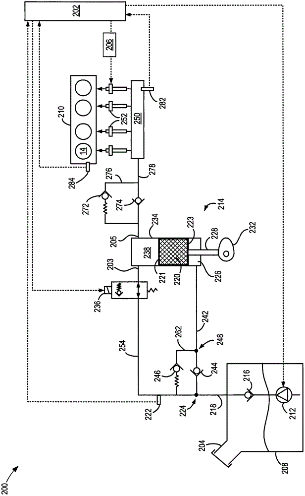
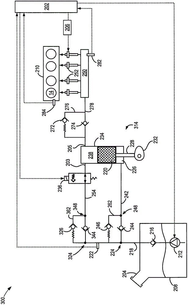
[0102] similar to figure 2 Referring to the first embodiment 200 of the fuel system, the third embodiment 300 of the fuel system also includes a first pressure relief valve 246 that is biasable to regulate the pressure in the step chamber 226 of the DI pump 314 . However, the pressure relief setting of the first pressure relief valve 246 may be different and different than the pressure relief setting of the second pressure relief valve 326 . In one example, the pressure relief setting of the first pressure relief valve 246 may be 5 bar and the pressure relief setting of the second pressure relief valve 326 may be 10 bar. In another example, the pressure relief setting of the first pressure relief valve 246 may be 8 bar and the pressure relief setting of the second pressure relief valve 326 may be 15 bar. Other pressure relief arrangements are possible without departing from the scope of the present application. For example, the pressure relief setting of the first pressure ...
no. 5 example 1000
[0145] The fifth embodiment 1000 includes a second fuel rail 1050 fluidly connected to each of the HPP 1014 and the LPP 212 . In the example shown, the second fuel rail 1050 may be a port injector fuel rail 1050 that supplies fuel to a plurality of port injectors 1052 . Thus, fuel may be provided to cylinders of engine 1010 via port injectors as well as direct injectors. Accordingly, engine 1010 may be a PFDI engine.
[0146] Controller 202 may independently drive each of port injectors 1052 via second injection driver 1006 . The controller 202, the second injection driver 1006, the first injection driver 206, and other suitable engine system controllers may comprise a control system. Although the second jetting driver 1006 is shown as being external to the controller 202 , it should be understood that in other examples the controller 202 may include the second jetting driver 1006 or may be configured to provide the functionality of the second jetting driver 1006 . Controll...
no. 8 example 1400
[0186] The eighth embodiment 1400 includes supplying fuel to the PFI rail 1050 through both sides of the pump piston 220 in the DI pump 1414, pressurizing the stepper chamber and compression chamber through one or more pressure relief valves, and supplying fuel to the stepper chamber through the compression chamber 238. Cavity 1426 provides a combination of fuels. In the eighth embodiment 1400 , the stepping chamber 1426 can be fluidly connected to the compression chamber 238 in the DI pump 1414 . Accordingly, additional check valves and pressure relief valves may be included that may not be included in previous embodiments.
[0187] Each of the step chamber 1426 and the PFI rail 1050 may receive fuel from the compression chamber 238 of the DI pump 1414 during the compression stroke when the SACV 236 is in the pass-through mode. Reverse flow fuel from the compression cavity may exit back through SACV 236 along pump passage 254 to node 1466 . At node 1466 , reverse flow fuel ...
PUM
 Abstract
Description
Claims
Application Information
 - R&D
- Intellectual Property
- Life Sciences
- Materials
- Tech Scout
- Unparalleled Data Quality
- Higher Quality Content
- 60% Fewer Hallucinations
Browse by: Latest US Patents, China's latest patents, Technical Efficacy Thesaurus, Application Domain, Technology Topic, Popular Technical Reports.
© 2025 PatSnap. All rights reserved.Legal|Privacy policy|Modern Slavery Act Transparency Statement|Sitemap|About US| Contact US: help@patsnap.com


