A positively loaded wind or hydroelectric generator

A technology for hydroelectric generators and generators, which is applied to wind power generators, hydroelectric power generation, and wind power generators at right angles to the wind direction. It can solve the problems of generator complexity, complex structure, increased size and weight, etc., and reduce the difficulty of production. and production costs, increase the range of applications, increase the effect of power and torque

Active Publication Date: 2018-12-11
梁玉杰
View PDF9 Cites 0 Cited by
  • Summary
  • Abstract
  • Description
  • Claims
  • Application Information

AI Technical Summary

Problems solved by technology

[0002] The main working principle of existing wind power or hydroelectric power generation is that external force (water power or wind power) pushes the blade of a rotating impeller to make it rotate to generate electricity. Since the surface of the blade must have an included angle with the external force when it is stressed, That is, the surface of the blade must be made into a slope to convert the external force in the vertical direction into the rotational force in the horizontal direction. Because the angle between the vertical force and the horizontal force is 90°, the best angle to convert the vertical force into a horizontal force is 45°, indicating that only 1 / 2 of the vertical force can be converted into horizontal force, that is, only half of the force has done useful work, which means that half of the limited resources that people have captured are wasted, due to design, structure, Influenced by factors such as production, more than that is wasted, not only that, but also use this included angle to achieve rotation. In order to obtain greater thrust, designers have to design the blades very long (the blades of wind turbines Already 8 meters to 15 meters or longer), while increasing the size and weight, it also limits the speed, increases the difficulty of production, complicates the generator, and ultimately leads to increased costs. Defects due to angles, The useful work is reduced, making the generator: high, large, heavy, complex structure and high cost, but the efficiency is not high, and the final result limits the development and application of hydraulic and wind power

Method used


Image

  • A positively loaded wind or hydroelectric generator
  • A positively loaded wind or hydroelectric generator
  • A positively loaded wind or hydroelectric generator

Examples


Embodiment 1

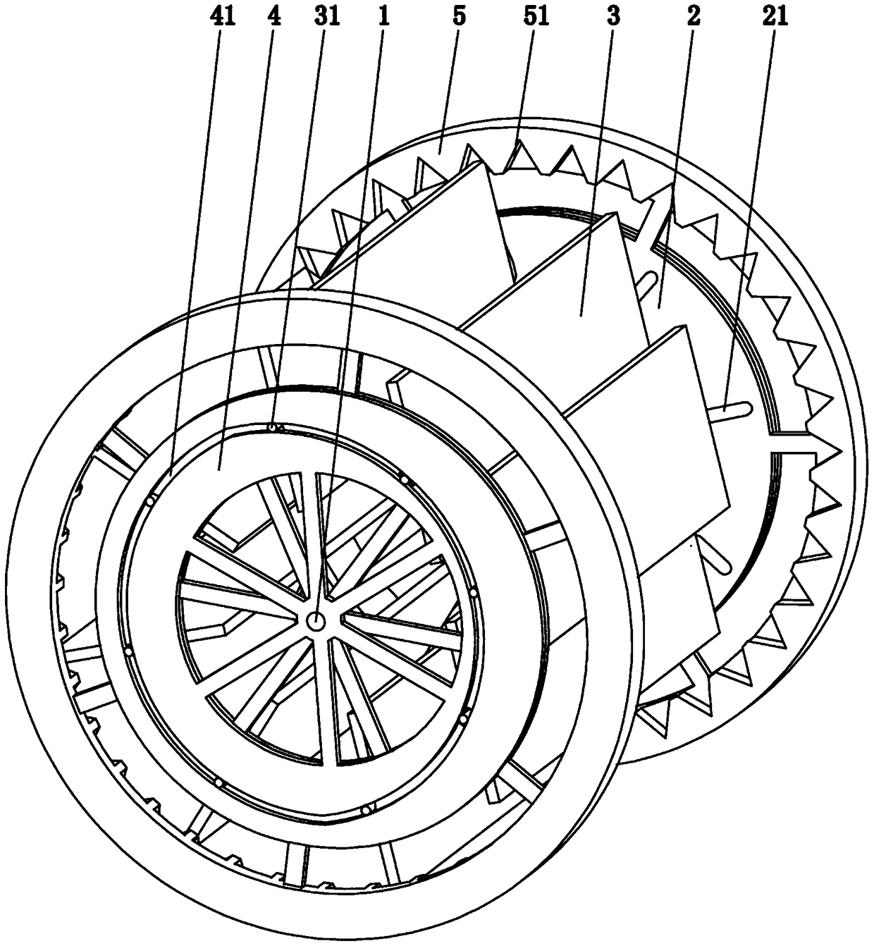
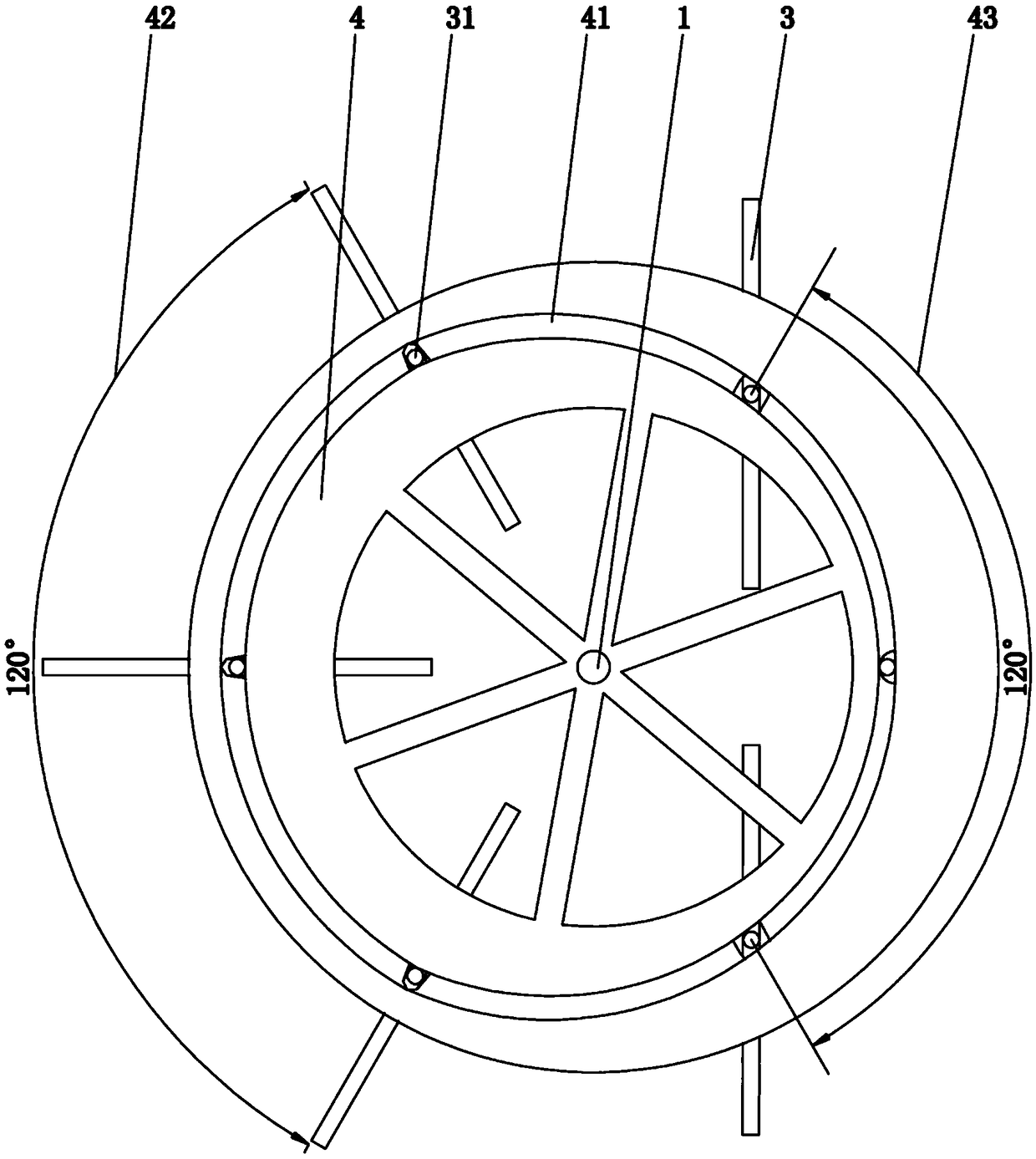
[0023] Embodiment 1, in a large-scale unit, it is necessary to use a blade 3 with a larger area to push, preferably a mandatory limit ring 5 is provided on the outer periphery of the support plate 2, and a number of blades are arranged on the inner edge of the mandatory limit ring 5. 3. Cooperating meshing teeth 51; the tooth height of said meshing teeth 51 is H, then H≤(D1-D2) / 2. Its main principle is the same as above, the difference is that when the blade 3 revolves to the free part 43 of the track plate 4 (ie the small-diameter circle part of the guide groove 41), the outer edge of the blade 3 breaks away from the restriction of the mandatory limit ring 5, so that The shaft 31 can rotate in the adapter hole 21; when the blade 3 revolves to the working area of ​​the work part 42 of the track plate 4 (that is, the large-diameter circle part of the guide groove 41), it is limited by the guide groove 41. The sub-shaft 31 of the sub-shaft 31 meshes with the revolving part 22 on...

Embodiment 2

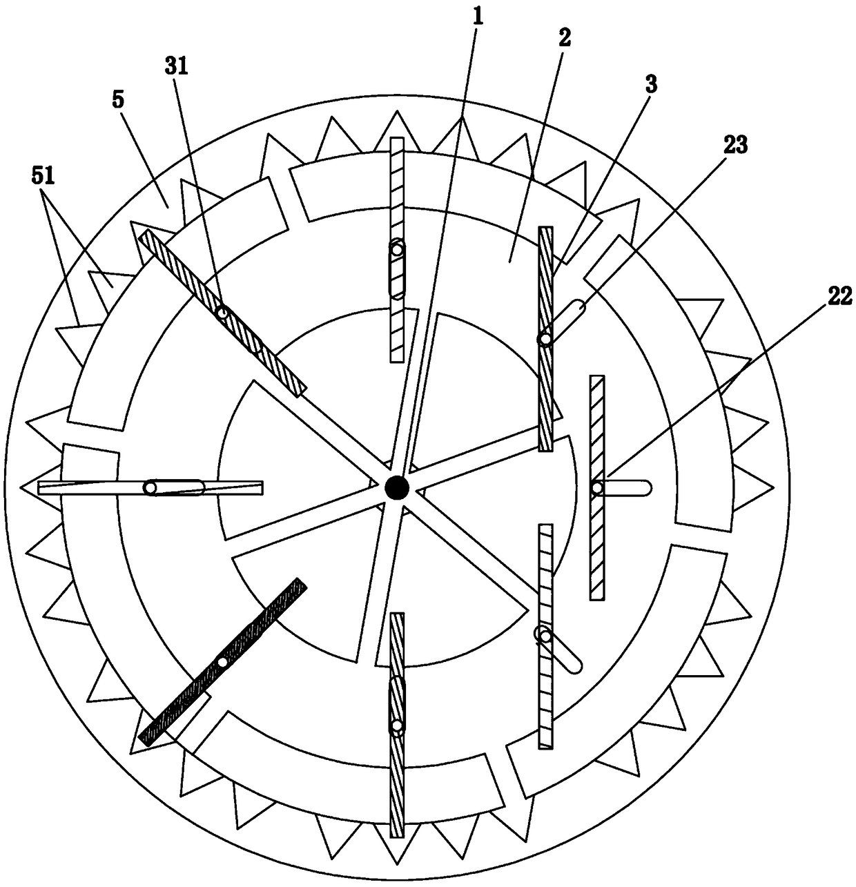
[0030] Embodiment 2, 4 groups of 8 blades 3 are arranged between the support plates 2, under the action of external wind force, one of the first group of blades 3 is located at 270°, at this point the track plate 4 pushes the blades 3 together with the sub-shaft 31 to At the position of the working part 42 (the far axis, that is, the great circle of the track plate 4), the tapered section of the factor shaft 31 enters the tapered groove of the support plate 2, which limits the rotation of the blade 3, and the front of the blade 3 is completely vertically affected by the external force. 3 When facing the wind or facing the water flow, there is no angle between the blade 3 and the external force, 100% of the external force is converted into torque to do work, and there is no energy waste. It can only revolve around the main shaft 1. The torque generated at this point is the largest. The other blade 3 of the same group is in the opposite 90° position. Due to the small circle of th...

Embodiment 3

[0031]Embodiment 3, when the main shaft 1 is placed horizontally, when the blade 3 rotates to the working part 42, due to the effect of gravity, the blade 3 can automatically fall into the mandatory limit ring 5, when the blade 3 rotates out of the working part, the gravity Under the action of the action, the blade 3 breaks away from the mandatory limit ring 5. Therefore, when the device is placed horizontally, the track plate 4 can be eliminated, further saving installation and manufacturing costs.


PUM


Abstract

The invention relates to the technical field of wind (water) power generation structures, in particular to a wind (water) power generator stressed in the forward direction. The wind (water) power generator comprises a generator spindle. The two ends of the spindle are provided with supporting plates which can rotate integrally with the two ends of the spindle. A plurality of blades are arranged between the two supporting plates. Sub spindles are arranged at the two ends of each blade. The supporting plates are provided with a plurality of matching holes which are in one-to-one correspondence with the blades. The sub spindles penetrate into the corresponding matching holes in the supporting plates. The states of the blades can be switched in the wind wheel rotating process, the blades can only achieve revolution on the rear half of the circumference (namely at the angle of 190-350 degrees) to generate thrust so that an acting area can be formed, the blades can only be rotated automatically on the front half of the circumference (namely at the angle of 10-170 degrees) so that a non-acting area can be formed, the spindle can be rotated under the resultant action to act, and the distance between the blades and the spindle and the sizes of the blades and the spindle can be changed so that the power and torque can be improved. The effective surface area of the blades is larger than that of a traditional impeller, practicability is greatly improved, manufacturing difficulty and production cost are lowered, and the range of the application field of the generator is widened.

Description

technical field [0001] The invention relates to the technical field of wind or hydroelectric power generation structures, in particular to a wind or hydroelectric generator under positive force. Background technique [0002] The main working principle of existing wind power or hydroelectric power generation is that external force (water power or wind power) pushes the blade of a rotating impeller to make it rotate to generate electricity. Since the surface of the blade must have an included angle with the external force when it is stressed, That is, the surface of the blade must be made into a slope to convert the external force in the vertical direction into the rotational force in the horizontal direction. Because the angle between the vertical force and the horizontal force is 90°, the best angle to convert the vertical force into a horizontal force is 45°, indicating that only 1 / 2 of the vertical force can be converted into horizontal force, that is, only half of the for...

Claims


Application Information

Patent Timeline
Patent Type & Authority Patents(China)
IPC IPC(8): F03B3/14F03D3/06
CPCF03B3/14F03D3/062Y02E10/20Y02E10/74Y02P70/50
Inventor 梁玉杰
Owner 梁玉杰
Why Eureka
Try Eureka