Solenoid valve diaphragm installation structure

An installation structure, solenoid valve technology, applied in the valve device, valve operation/release device, diaphragm and other directions, can solve the problems of diaphragm tear, relay failure, damage, etc., to simplify the structure, prolong the service life, reduce the damage effect

Inactive Publication Date: 2017-01-04
贵州新安航空机械有限责任公司
View PDF6 Cites 3 Cited by
  • Summary
  • Abstract
  • Description
  • Claims
  • Application Information

AI Technical Summary

Problems solved by technology

[0003] The electromagnetic relay of the oxygen concentrator is an important part to increase the oxygen concentration of the oxygen concentrator. When the original electromagnetic relay is in use, because the edge of the diaphragm is pressed by the push rod, the middle of the diaphragm is stretched, and the diaphragm is easily torn and damaged. , resulting in relay failure and short service life

Method used


Image

  • Solenoid valve diaphragm installation structure

Examples


Embodiment

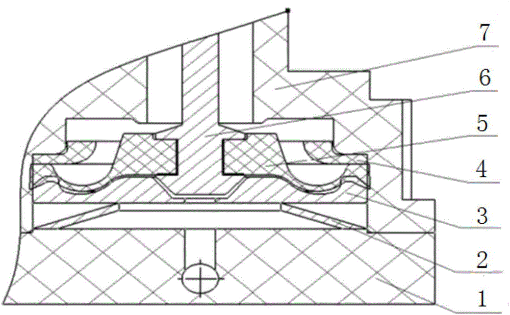
[0019] The arrangement of the elastic element 2 transfers the thrust of the push rod 6 and the pressure on the upper diaphragm 5 to the elastic element 2, and the elastic deformation of the elastic element 2 protects the upper diaphragm 5 from tearing. The butterfly spring adopted in the technical solution has an initial elastic force of zero and relatively high stiffness, ranging from 130N / mm to 150N / mm. The support seat 3 corresponds to the structure of the upper diaphragm 5 and the end of the push rod 6. The diaphragm installation groove supports and protects the upper diaphragm 5. The support frame 4 between the upper diaphragm 5 and the valve body 7 can The edge of upper diaphragm 5 is compressed.

[0020] When the relay is not working, the elastic element 2 has an initial elastic force of zero and is fixed between the cover plate 1 and the support base 3 . The push rod 6 is stressed, which generates pressure on the edge of the upper diaphragm 5, and the edge part of the...


PUM


Abstract

The invention discloses a solenoid valve diaphragm installation structure, which belongs to the technical field of electromagnetic relays, and comprises two opposite cover plates and a valve body arranged between the cover plates. A push rod is arranged in the valve body; upper diaphragms are arranged around the push rod; a support seat is arranged between the upper diaphragms and the cover plates; elastic components are arranged between the support seat and the cover plates; support brackets are arranged on edges between the upper diaphragms and the valve body. According to the technical scheme, the support seat is arranged between the cover plates and the upper diaphragms, so that the structure of each cover plate is simplified; the elastic components are arranged between the support seat and the cover plates, so that the pressure deformation borne by the push rod and the upper diaphragms is transferred to the elastic components on the lower parts; with diaphragm installation slot structures on the upper diaphragm parts, the push rod and the upper diaphragms are stressed in a balance way, so that the damage caused by pressure force on the diaphragms is reduced, and the service life of an electromagnetic relay is prolonged.

Description

technical field [0001] The invention belongs to the technical field of electromagnetic relays, and relates to a component of an electromagnetic relay of a medical device, in particular to a diaphragm installation structure of an electromagnetic valve. Background technique [0002] At present, the electromagnetic relay of the oxygen concentrator has been widely used in the oxygen concentrator. With the development of technology and the improvement of human's attention to their own health, the household oxygen concentrator has been widely used in the family. [0003] The electromagnetic relay of the oxygen concentrator is an important part to increase the oxygen concentration of the oxygen concentrator. When the original electromagnetic relay is in use, because the edge of the diaphragm is pressed by the push rod, the middle of the diaphragm is stretched, and the diaphragm is easily torn and damaged. , resulting in relay failure and short service life. Contents of the invent...

Claims


Application Information

Patent Timeline
Patent Type & Authority Applications(China)
IPC IPC(8): F16K31/06F16K7/17
CPCF16K31/0672F16K7/17
Inventor 鞠洪福
Owner 贵州新安航空机械有限责任公司
Why Eureka
Try Eureka