Simple evaporator

An evaporator, a simple technology, applied in the field of simple evaporators, can solve the problems of difficult recombination, evaporator leakage, and easy blockage of the medium, and achieve the effect of solid one-piece molding, meeting heat exchange requirements, and easy cleaning and maintenance

Inactive Publication Date: 2017-01-04
TIANJIN BOTAI HEAT EXCHANGE EQUIP
View PDF0 Cites 3 Cited by
  • Summary
  • Abstract
  • Description
  • Claims
  • Application Information

AI Technical Summary

Problems solved by technology

[0002] In modern production and life, evaporators are widely used in various fields, and the requirements for their use are also increasing. As a type of evaporator, plate heat exchangers have always been favored by various industries, with high frequency of use and effective Preferably, it is a new type of high-efficiency heat exchanger that is stacked by a series of metal sheets with a certain corrugated shape. A thin rectangular channel is formed between various plates. The plate heat exchanger is liquid-liquid, liquid-vapor It is an ideal equipment for heat exchange. It has the characteristics of high heat exchange efficiency, small heat loss, compact and light structure, small footprint, wide application, and long service life. However, the flow channel design of the existing plate evaporator equipment has not yet reached In an ideal state, there is a dead zone, and the medium is easy to block, which often causes the evaporator to leak and not flow, and when it is repaired, it often encounters problems such as difficult disassembly and reassembly. In view of this situation, this The invention proposes a simple evaporator, which meets the heat exchange requirements and improves the heat exchange efficiency. The simple and compact structure facilitates equipment cleaning and maintenance, and has a good sealing effect, which is suitable for widespread promotion in this industry.

Method used

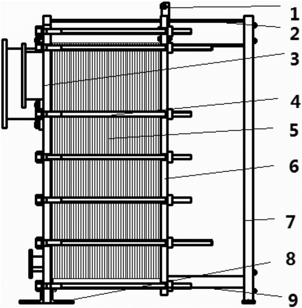
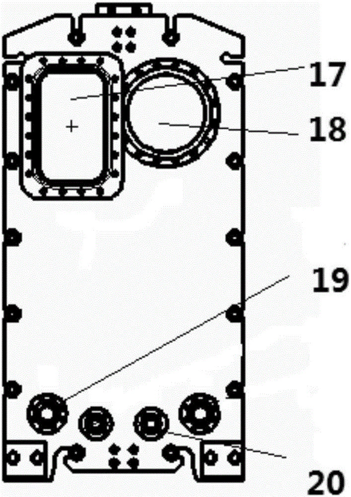
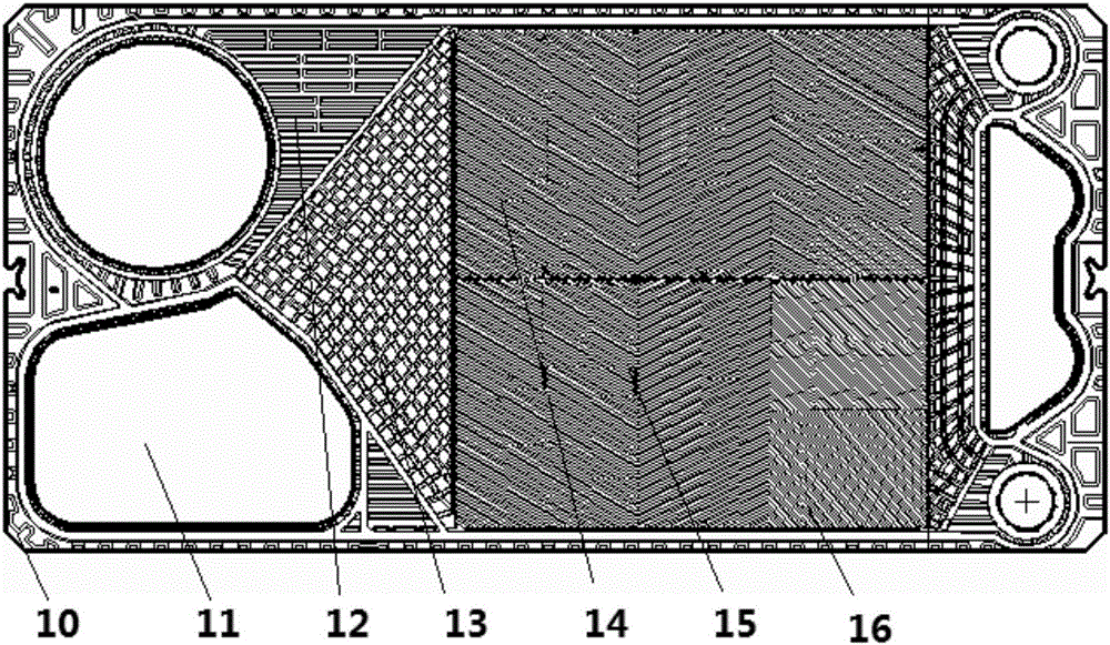

Image

  • Simple evaporator
  • Simple evaporator
  • Simple evaporator

Examples


Embodiment Construction

[0034] It should be noted that the embodiments of the present invention and the features in the embodiments can be combined with each other if there is no conflict.

[0035] In the description of the present invention, it should be understood that the terms "center", "longitudinal", "transverse", "upper", "lower", "front", "rear", "left", "right", " The orientation or positional relationship indicated by "vertical", "horizontal", "top", "bottom", "inner", "outer" etc. is based on the orientation or positional relationship shown in the drawings, and is only for the convenience of describing the present invention and The description is simplified, rather than indicating or implying that the pointed device or element must have a specific orientation, be constructed and operated in a specific orientation, and therefore cannot be understood as a limitation of the present invention. In addition, the terms "first", "second", etc. are only used for descriptive purposes, and cannot be und...


PUM


Abstract

The invention provides a simple evaporator which comprises a fixing plate, a heat exchange unit, a moveable plate and a lateral bracket, wherein the heat exchange unit, the moveable plate and the lateral bracket are successively arrayed on a side wall of the fixing plate; U-shaped slots are arranged on the peripheries of the fixing plate and the moveable plate; the heat exchange unit comprises a plurality of heat exchange sets and a sealing gasket; corner holes for medium runners are formed in the four corners of a heat exchange plate; a flow guide area, a flow-splitting area and a heat exchange area are successively distributed on the heat exchange plate along the corner holes toward the center of the heat exchange plate; the heat exchange area is divided into a first heat exchange area and a second heat exchange area by taking the vertical central line of the heat exchange plate as a datum; the corner holes include a first medium inlet, a first medium outlet, a second medium inlet and a second medium outlet arranged in the flow guide area. The simple evaporator provided by the invention can meet the heat exchange requirement and can increase the heat exchange efficiency; a simple and compact structure is adopted, so that the device can be conveniently cleaned and maintained; the detaching is convenient; the heat exchange plate can be conveniently added and reduced; the sealing effect is better; the simple evaporator is fit for industrial wide popularization.

Description

Technical field [0001] The invention belongs to the technical field of heat exchangers, and in particular relates to a simple evaporator. Background technique [0002] In modern production and life, evaporators are widely used in various fields, and the relative requirements for their use are also increasing. As a kind of evaporator, plate heat exchangers have always been favored by various industries, with high frequency of use and effects. Preferably, it is a new type of high-efficiency heat exchanger formed by stacking a series of metal sheets with a certain corrugated shape. Thin rectangular channels are formed between various plates. The plate heat exchanger is liquid-liquid and liquid-vapor. The ideal equipment for heat exchange, it has the characteristics of high heat exchange efficiency, small heat loss, compact and lightweight structure, small footprint, wide application, long service life, etc., but the existing plate evaporator equipment flow channel design has not yet...

Claims


Application Information

Patent Timeline
Patent Type & Authority Applications(China)
IPC IPC(8): F28D9/04F28F11/00
CPCF28D9/0037F28D9/04F28F11/00
Inventor 管仁行何娟崔颖
Owner TIANJIN BOTAI HEAT EXCHANGE EQUIP
Why Eureka
Try Eureka