Automatic liquid flow rate stabilizer based on jet cavitation

An automatic and stable liquid flow technology, applied in jet pumps, machines/engines, non-displacement pumps, etc., can solve the problems of long fluctuation time of flow set value, low flow stability accuracy, complex device structure, etc., to achieve Improve the ability to adapt to the medium, improve the accuracy of flow control, and improve the effect of controllability

Active Publication Date: 2017-05-31
WUHAN UNIV
View PDF7 Cites 5 Cited by
  • Summary
  • Abstract
  • Description
  • Claims
  • Application Information

AI Technical Summary

Problems solved by technology

[0003] Whether it is electronic control or automatic control, the existing liquid flow stabilization device is a gradual flow stabilization device, and there is a problem that the adjustment time is too long to cause the flow to fluctuate between the set value for too long, the fluctuation range is large, and the device structure is complicated , poor maintainability
The automatic control device similar to the pilot-operated flow control valve also has the problem of low flow stability and accuracy
These devices are not suitable for occasions that require very high flow stability and response speed

Method used


Image

  • Automatic liquid flow rate stabilizer based on jet cavitation
  • Automatic liquid flow rate stabilizer based on jet cavitation
  • Automatic liquid flow rate stabilizer based on jet cavitation

Examples


Embodiment Construction

[0029] The present invention will be further described below in conjunction with the accompanying drawings and embodiments.

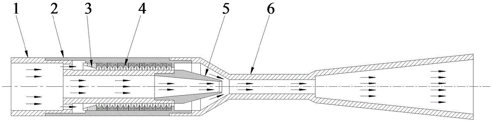
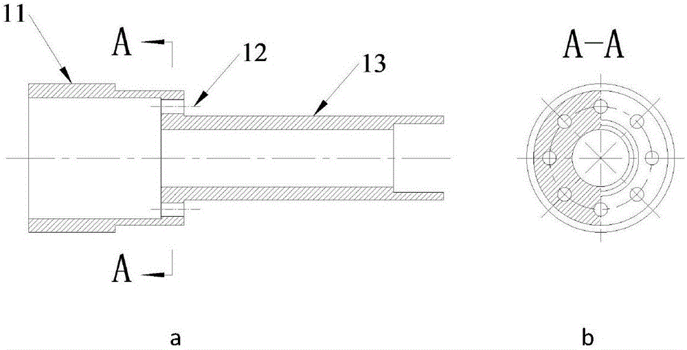
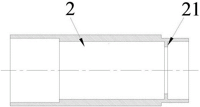
[0030] An automatic liquid flow stabilization device based on jet cavitation, comprising a supply pipe 1, a tubular suction chamber 2 and a cavitation chamber 6 connected coaxially in sequence along the direction of water flow; The larger-diameter total incoming flow pipe 11 and the smaller-diameter nozzle connecting pipe 13; the outlet end of the nozzle connecting pipe 13 is provided with a nozzle 5; the nozzle connecting pipe 13 is located in the suction chamber 2; the cavitation The cavity 6 includes a constriction tube 61, a throat 62 and a diffuser tube 63 connected together along the direction of water flow; one end of the suction chamber 2 is connected to the main flow pipe 11 through threads, and the other end is connected to the constriction tube 61 through threads; A number of suction chamber supply holes 12 communicated with the suction chamb...


PUM


Abstract

The invention discloses an automatic liquid flow rate stabilizer based on jet cavitation. The device comprises a feed pipe, a suction chamber, a stop collar, decompression rings, a nozzle and a cavitation cavity. The device firstly divides a flow from upstream into two parts, wherein one part is sprayed into the cavitation cavity after being accelerated and decompressed via the nozzle, while the other part also flows into the cavitation cavity after being decompressed by the decompression rings connected in series. The two flows are converged again in a shrinkable pipe in the cavitation cavity, the two flows generate a vortex and then generates a relatively large cavitation to cause cavitation inception, then violent cavitation clouds are rapidly formed in a choke to congest the whole choke, and gradually collapsed after being continuously developed to a diffusion pipe; the choke is full of the cavitation clouds, so that fluctuation of outlet pressure cannot be transmitted to the upstream of the choke, and thus a pressure difference between the feed pipe and the shrinkable pipe is always constant, and flow rate stability is achieved. The device provided by the invention is extremely rapid in response speed, invention high in flow rate stability, simple in structure, high in maintainability, strong in adaptation capacity to medium, and capable of being used in large scale.

Description

technical field [0001] The invention belongs to the technical field of liquid flow control, and in particular relates to a brand-new liquid automatic flow stabilization device based on jet cavitation. Background technique [0002] Existing liquid flow stabilizing devices can be roughly divided into two types: electric control and automatic control. Electric control requires the use of electric signals to drive the feedback unit for control. Most of them use the form of cooperation between the electric control valve and the flow sensor. When the flow sensor senses the flow change, it transmits the signal to the control center, and the control center then sends an action to the electric control valve. instruction, and then the flow control is realized by the action of the electronically controlled valve until the flow returns to the set value. The electronically controlled constant flow water valve disclosed by the publication number CN1865747A is exactly this type. Self-cont...

Claims


Application Information

Patent Timeline
Patent Type & Authority Applications(China)
IPC IPC(8): F04F5/10F04F5/44F04F5/46F04F5/48
CPCF04F5/10F04F5/44F04F5/46F04F5/48
Inventor 龙新平章君强季斌
Owner WUHAN UNIV
Why Eureka
Try Eureka