Radiating pipe base and manufacturing method thereof

A manufacturing method and heat pipe technology, applied in heat exchange equipment, heat exchanger shell, heat exchanger fixing and other directions, can solve the problem of affecting heat dissipation effect, inconvenient movement, unfavorable heat sink, heat pipe cleaning, replacement or maintenance, etc. problem, to achieve the effect of high-efficiency mass production and convenient assembly

Active Publication Date: 2017-01-04
ANHUI TIANXIANG AIR CONDITIONING SCI & TECH CO LTD
View PDF5 Cites 1 Cited by
  • Summary
  • Abstract
  • Description
  • Claims
  • Application Information

AI Technical Summary

Problems solved by technology

[0002] The heat dissipation effect of the radiator mainly depends on the heat dissipation pipe and heat sink, but after a long time of use, the heat dissipation effect will be affected by the accumulation of dust
Many radiator pipe sockets are relatively fixed, not only inconvenient to move, but also cumbersome to disassemble, which is not conducive to the cleaning, replacement or maintenance of heat sinks and heat pipes

Method used


Image

  • Radiating pipe base and manufacturing method thereof
  • Radiating pipe base and manufacturing method thereof

Examples


Embodiment

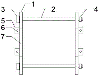
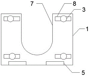
[0023] A heat dissipation pipe seat, comprising a square plate 1 and a straight rod 2, a U-shaped groove 7 is formed on the upper part of one side surface of the square plate 1, and a U-shaped groove 7 is formed on the left and right sides of the U-shaped groove 7 on the side surface of the square plate 1 There is a pair of rectangular bar holes 8, the lower part of one side of the square plate 1 is brazed with a fixing seat 5, the upper surface of the fixing seat 5 is provided with a mounting hole 6, and one end of the straight rod 2 is inserted into the rectangular bar hole 8, and one end of the straight rod 2 is fixedly connected with a round cake 3, the outside of the other end of the straight rod 2 is provided with an external thread and an anti-skid nut 4 is installed, and the diameter of the straight rod 2 is smaller than the width of the rectangular hole 8 , the diameter of the round cake 3 is greater than the width of the rectangular hole 8, the number of the square pl...


PUM

PropertyMeasurementUnit
thicknessaaaaaaaaaa
thicknessaaaaaaaaaa

Abstract

The invention discloses a radiating pipe base. The radiating pipe base comprises square plates and straight rods; a U-shaped groove is formed in the upper portion of the surface of one side of each square plate; a pair of rectangular strip-shaped holes are formed in the positions, on the left side and the right side of each U-shaped groove, of the surface of one side of the corresponding square plate; the lower portions of one sides of the square plates are in brazing connection with fixed seats; the upper surfaces of the fixed seats are provided with installation holes; one ends of the straight rods are connected into the rectangular strip-shaped holes in an inserted mode and fixedly connected with round disks, and the outer sides of the other ends of the straight rods are provided with outer threads and anti-slide nuts. The radiating pipe base is formed by assembling the square plates, the rectangular strip-shaped holes and the straight rods in a matched mode, the relative positions of the straight rods and the rectangular strip-shaped holes can be adjusted to adapt to the size of a radiating fin, and the radiating fin is fixed in the radiating pipe base in the mode that the four corners of the radiating fin are clamped and fixed; layout of radiating pipes cannot be influenced by the U-shaped grooves formed in the square plates; and in addition, disassembling, maintaining and assembling are all very convenient.

Description

technical field [0001] The invention belongs to the field of radiators, and more specifically relates to a heat dissipation pipe base. At the same time, the invention also relates to a manufacturing method of the heat dissipation pipe base. Background technique [0002] The heat dissipation effect of the radiator mainly depends on the heat dissipation pipe and the heat dissipation fin. However, after a long time of use, the heat dissipation effect will be affected due to the accumulation of dust. Many radiator pipe sockets are relatively fixed, which is not only inconvenient to move, but also cumbersome to disassemble, which is not conducive to the cleaning, replacement or maintenance of heat sinks and heat pipes. Contents of the invention [0003] The purpose of the present invention is to solve the shortcomings in the prior art, and propose a heat dissipation pipe base and its manufacturing method. [0004] To achieve the above object, the present invention provides th...

Claims


Application Information

Patent Timeline
Patent Type & Authority Applications(China)
IPC IPC(8): F28F9/013B23P15/26
CPCB23P15/26F28F9/0131F28F2275/06F28F2275/20
Inventor 骆宣佐
Owner ANHUI TIANXIANG AIR CONDITIONING SCI & TECH CO LTD
Why Eureka
Try Eureka