
Electronic device and manufacturing method

A technology of electronic equipment and circuit board, applied in the electronic field, can solve the problems of occupying electronic equipment, affecting the layout of electronic equipment, large space, etc., and achieve the effect of saving occupied space

Active Publication Date: 2021-03-16
BEIJING XIAOMI MOBILE SOFTWARE CO LTD
View PDF14 Cites 0 Cited by
  • Summary
  • Abstract
  • Description
  • Claims
  • Application Information

AI Technical Summary

Problems solved by technology

However, the metal shield will occupy a large space of the electronic equipment and affect the internal layout of the electronic equipment

Method used


Image

  • Electronic device and manufacturing method
  • Electronic device and manufacturing method
  • Electronic device and manufacturing method

Examples


Embodiment Construction

[0030] The following will clearly and completely describe the technical solutions in the embodiments of the present disclosure with reference to the accompanying drawings in the embodiments of the present disclosure. Apparently, the described embodiments are part of the embodiments of the present disclosure, not all of them. Based on the embodiments in the present disclosure, all other embodiments obtained by persons of ordinary skill in the art without making creative efforts belong to the protection scope of the present disclosure.

[0031] In order to make the purpose, technical solution and advantages of the present disclosure clearer, the implementation manners of the present disclosure will be further described in detail below in conjunction with the accompanying drawings.

[0032] Reference will now be made in detail to the exemplary embodiments, examples of which are illustrated in the accompanying drawings. When the following description refers to the accompanying dra...


PUM

PropertyMeasurementUnit
diameteraaaaaaaaaa
diameteraaaaaaaaaa
diameteraaaaaaaaaa

Abstract

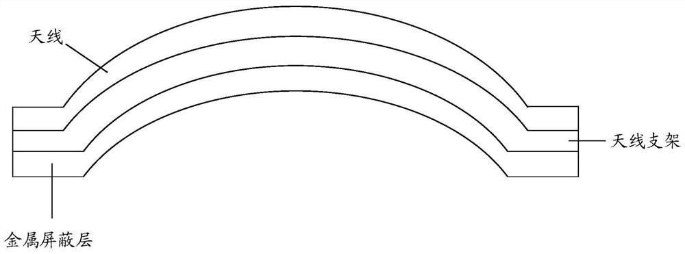
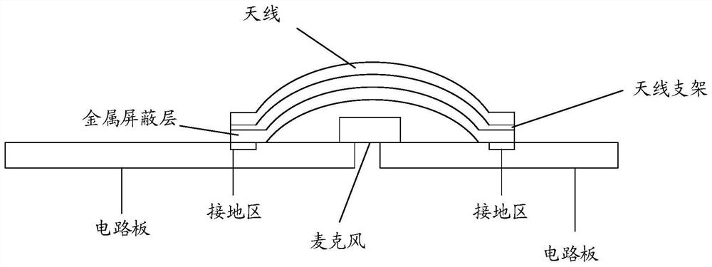
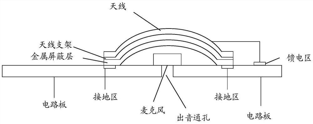
The invention provides electronic equipment and a manufacturing method thereof, and belongs to the technical field of electronics. A microphone and an antenna support are arranged on a circuit board.The first side surface of the antenna support and the circuit board form an internal cavity, and the microphone is located in the internal cavity. A metal shielding layer formed through lasering is arranged on the first side surface of the antenna support. The metal shielding layer covers the microphone. An antenna is located on the second side surface of the antenna support. The first side surface of the antenna support is opposite to the second side surface of the antenna support. The metal shielding layer is connected with a grounding area on the circuit board. When the electromagnetic waveradiates into the antenna support, the metal shielding layer on the antenna support can conduct the electromagnetic wave to the grounding area so as to absorb the electromagnetic wave and realize thefunction of shielding the electromagnetic wave. The metal shielding layer is directly arranged on the antenna support through lasering and a metal shielding cover does not need to be additionally arranged. The thickness of the metal shielding layer is far less than the thickness of the metal shielding cover so as to save the occupied space without affecting the layout of the electronic equipment.

Description

technical field [0001] The present disclosure relates to the field of electronic technology, in particular to an electronic device and a manufacturing method. Background technique [0002] With the development of electronic technology, more and more components are configured in electronic equipment, and more and more functions can be realized. The circuit board, the microphone and the antenna module are all essential parts of the electronic equipment, and the microphone and the antenna module are usually arranged on the circuit board. [0003] Due to the limited internal space of the electronic device and the short distance between the antenna module and the microphone, the wireless signal transmitted by the antenna module will interfere with the voice signal received by the microphone, resulting in noise in the voice signal. [0004] In order to avoid interference, when making electronic equipment, a metal shield is provided in the electronic equipment, and the metal shiel...

Claims


Application Information

Patent Timeline
Patent Type & Authority Patents(China)
IPC IPC(8): H01Q1/22H01Q1/24H01Q1/52H01Q1/50H01Q1/38B23K26/362
CPCB23K26/362H01Q1/22H01Q1/2266H01Q1/243H01Q1/38H01Q1/50H01Q1/526
Inventor 金修禄
Owner BEIJING XIAOMI MOBILE SOFTWARE CO LTD
Learn More