
Optical fiber tilt angle sensor and wavelength division multiplexing method thereof

An inclination sensor and wavelength division multiplexing technology, applied in the direction of instruments, measuring inclination, measuring devices, etc., can solve the problems that the measurement accuracy is difficult to meet the measurement requirements, and achieve the goals of reducing measurement costs, simple sensing principle, and avoiding deviation Effect

Inactive Publication Date: 2017-01-04
WUHAN UNIV OF TECH
View PDF7 Cites 6 Cited by
  • Summary
  • Abstract
  • Description
  • Claims
  • Application Information

AI Technical Summary

Problems solved by technology

The above-mentioned inventions all use fiber gratings as sensing elements, so they have the advantages of good anti-electromagnetic interference, strong reusability, convenient networking, and self-compensation for temperature, but there is a problem that the measurement accuracy cannot meet the measurement requirements when the measurement range is large.

Method used


Image

  • Optical fiber tilt angle sensor and wavelength division multiplexing method thereof
  • Optical fiber tilt angle sensor and wavelength division multiplexing method thereof
  • Optical fiber tilt angle sensor and wavelength division multiplexing method thereof

Examples


Embodiment Construction

[0020] The present invention will be further described below in conjunction with specific examples and drawings.

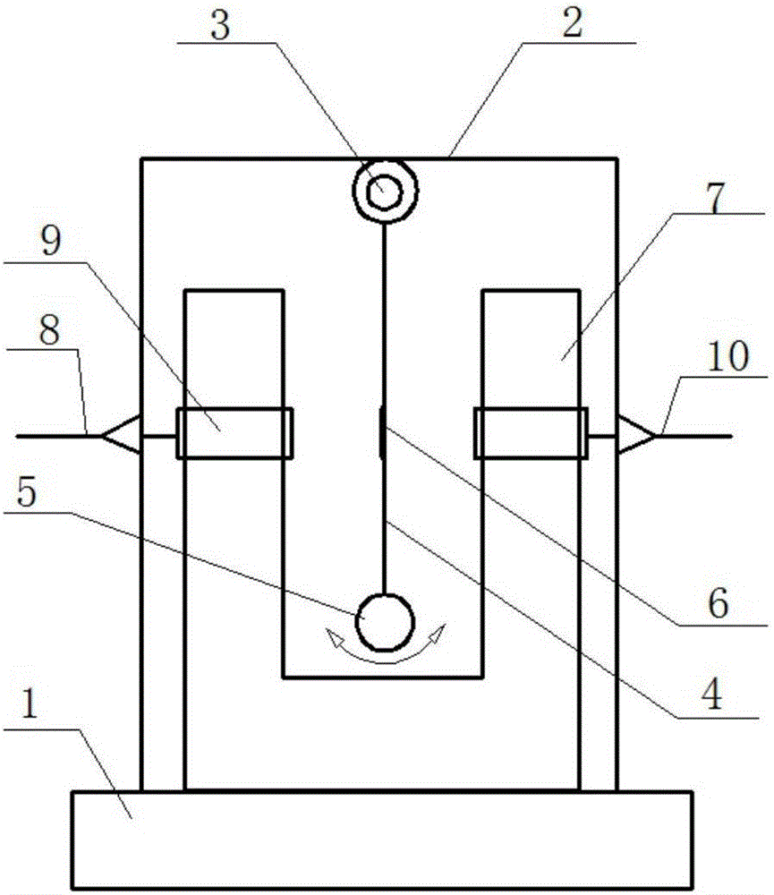
[0021] The present invention provides an optical fiber inclination sensor, such as figure 1 As shown, it includes a housing 2, a rotating shaft 3, a swing arm 4, and a pendulum 5, wherein the rotating shaft 3 is arranged in the upper part of the housing 2, and the pendulum 5 is connected to the rotating shaft 3 through the swing arm 4 to form a structure that can only swing in a single plane For a single pendulum system, the swing arm 4 is provided with a central hole, and a filter 6 is provided on the central hole. The two sides of the filter 6 are respectively provided with a light input end 8 and an output end 10, and the filter 6 A collimator 9 is provided between the input end and between the filter 6 and the output end, and the filter 6 is coaxial with the collimator 9.

[0022] Further, it also includes a mounting base 1 on which the housing 2 is fixed.

[0023] ...


PUM


Abstract

The invention provides an optical fiber tilt angle sensor which comprises a shell, a rotating shaft, a swing arm and a pendulum bob. The rotating shaft is arranged at the upper portion inside the shell. The pendulum bob is connected to the rotating shaft through the swing arm to form a single-pendulum system which can only swing inside the unique plane. A center hole is formed in the swing arm. An optical fiber is arranged in the center hole. The two sides of the optical fiber are provided with an optical input end and an optical output end respectively. A collimator is arranged between the optical fiber and the input end, and a collimator is arranged between the optical fiber and the output end; the optical fiber and the collimators are coaxial. The optical fiber is adopted as a sensing element of the tilt angle sensor. The optical fiber tilt angle sensor is simple in sensing principle, high in measuring precision and good in long-term stability; due to adoption of the rotating shaft, the pendulum bob can only swing inside the unique plane, and deflection of the optical fiber during measurement is avoided.

Description

Technical field [0001] The invention belongs to the technical field of inclination angle measurement and optical fiber sensing for large-scale engineering structures, and specifically relates to an optical fiber inclination angle sensor and a wavelength division multiplexing method thereof. Background technique [0002] Large structures on the ground, such as high-rise buildings, bridges, dams, and large equipment, must constantly monitor their inclination angles relative to the plumb line. At present, the inclination angle measurement sensor can be divided into three types: gas pendulum, liquid pendulum, and solid pendulum from the working principle. The gas pendulum has strong resistance to vibration or impact, but the gas motion control is more complicated and the measurement accuracy is not high. The liquid pendulum tilt sensor system is stable, and it is widely used in high-precision systems, but the measurement range is small and the measurement environment is relatively h...

Claims


Application Information

Patent Timeline
IPC IPC(8): G01C9/00
CPCG01C9/00
Inventor 南秋明王立新梁磊李盛唐健冠潘建军
Owner WUHAN UNIV OF TECH
Learn More