
Method for using an integrated device for detecting and eliminating transformer residual magnetism

A transformer and transformer low-voltage side technology, applied in the direction of the magnitude/direction of the magnetic field, magnetic objects, magnetic performance measurement, etc., can solve the problems of increasing the reactive power loss of the transformer, the transformer cannot be put into operation smoothly, and loses meaning

Active Publication Date: 2019-03-22
STATE GRID HEBEI ELECTRIC POWER RES INST +2
View PDF5 Cites 0 Cited by
  • Summary
  • Abstract
  • Description
  • Claims
  • Application Information

AI Technical Summary

Problems solved by technology

The large core residual magnetism will cause the transformer to generate a large value and long time excitation inrush current when it is put into operation, which will cause the malfunction of the relay protection device and make the transformer unable to be put into operation smoothly; the vibration and noise of the transformer will increase, which will affect the transformer. It will affect the structural parts of the transformer and shorten the overhaul period of the transformer; make the input and output voltage and current data of the transformer inaccurate, which will interfere with many routine test items, and even make some tests meaningless; A large number of even-order harmonics are generated in the current, which not only increases the reactive power loss of the transformer, but also makes the transformer a harmonic source of the power grid, which affects the quality of power supply. At the same time, it may also form an inrush current with cascaded or parallel transformers, which threatens once Safe and stable operation of equipment

Method used


Image

  • Method for using an integrated device for detecting and eliminating transformer residual magnetism
  • Method for using an integrated device for detecting and eliminating transformer residual magnetism
  • Method for using an integrated device for detecting and eliminating transformer residual magnetism

Examples


Embodiment Construction

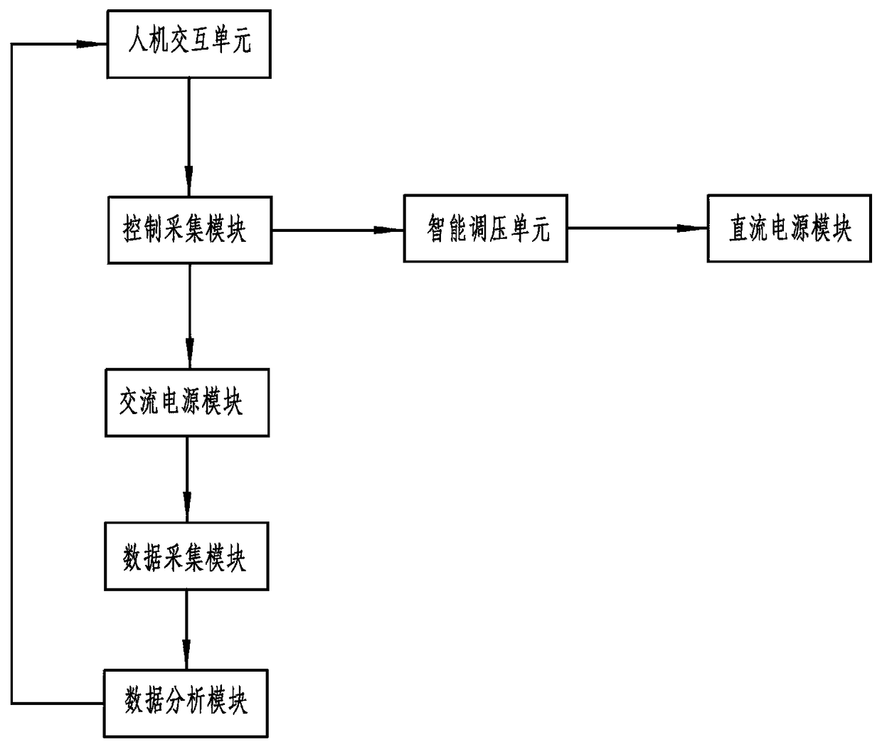
[0019] as attached figure 1 As shown, the present invention includes an AC power supply module connected to the low-voltage side winding of the transformer, a power conversion module for converting AC and DC, an intelligent voltage regulation unit, a DC power supply module whose input terminal is connected to the output terminal of the intelligent voltage regulation unit, and human A computer interaction unit, a control acquisition module connected with the human-computer interaction unit, a data acquisition module for collecting output voltage and current data, and a data analysis module connected with the data acquisition module, and the output terminal of the DC power supply module is connected with the high voltage winding of the transformer. The human-computer interaction unit includes an interface module, a display module and a keyboard module. The model of the AC power supply module is DYYJL-1, the model of the intelligent voltage regulation unit is DYYTY-1, the model o...


PUM


Abstract

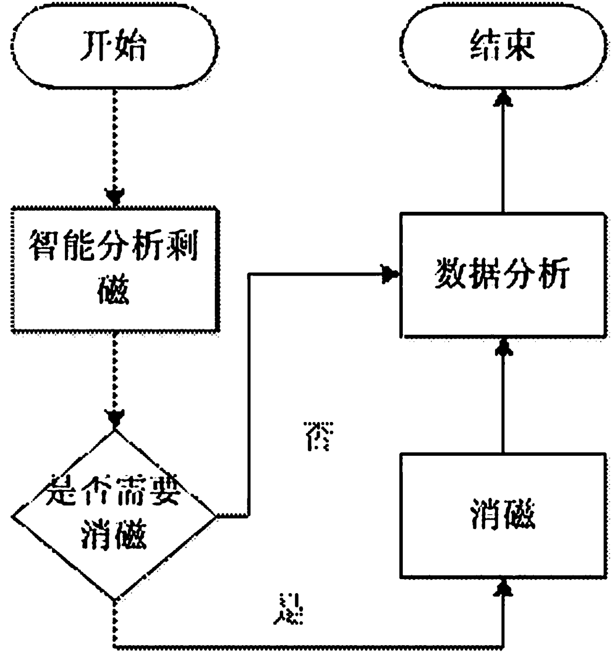
The invention relates to an integrated apparatus for detecting and eliminating the residual magnetism of a transformer and a method for using the same. The apparatus comprises an AC power supply module, an intelligent voltage regulation unit, a DC power supply module, a human-machine interaction unit, a control acquisition module, a data acquisition module and a data analysis module. The output terminal of the DC power supply module is connected with the high-voltage winding of the transformer. The human-machine interaction unit, the control acquisition module, the AC power supply module, the data acquisition module and the data analysis system can intelligently detect whether the transformer needs demagnetization. The DC power supply module is used for intelligent demagnetization. The intelligent voltage regulation unit can adjust the current of the DC power supply module at any time so as to effectively demagnetize the transformer. The human-machine interaction unit has a display module, may display demagnetization results in a visualized manner, and performs comparison with historical data to analyze a data development law.

Description

technical field [0001] The invention relates to the technical field of power equipment, in particular to a method for using an integrated device for detecting and eliminating residual magnetism of a transformer. Background technique [0002] After the DC test of a large-scale power transformer, a large amount of residual magnetism may remain in the iron core, which will cause a large value and a long time excitation inrush current when the transformer is put into operation, resulting in the malfunction of the relay protection device. Related primary equipment has a greater impact. [0003] There are two main reasons for the generation of transformer residual magnetism: one is that magnetic materials such as transformer iron core have hysteresis effect, that is, the change of magnetic induction intensity B always lags behind the change of magnetic field intensity H; the other is that the winding DC resistance test before the transformer is put into operation The external DC ...

Claims


Application Information

Patent Timeline
Patent Type & Authority Patents(China)
IPC IPC(8): G01R33/02G01R33/12H01F13/00
CPCG01R33/02G01R33/12H01F13/006
Inventor 刘振陈志勇刘宏亮张建军庞先海景皓
Owner STATE GRID HEBEI ELECTRIC POWER RES INST
Learn More