Method and system for degaussing power transformer

A power transformer and degaussing technology, which is applied in the field of power transformers, can solve the problems of increased magnetic flux leakage, insignificant degaussing effect, immaturity, etc., and achieve effective degaussing and obvious degaussing effect

Active Publication Date: 2014-03-12
STATE GRID CORP OF CHINA +4
View PDF4 Cites 9 Cited by
  • Summary
  • Abstract
  • Description
  • Claims
  • Application Information

AI Technical Summary

Problems solved by technology

[0002] The power transformer is one of the important components of the power grid. After the direct resistance test of the power transformer, there will be a certain residual magnetic flux in the iron core. Due to the existence of the residual magnetic flux, a large number of harmonics will be generated in the excitation current, which not only increases the The reactive power consumption of the power transformer may also cause the malfunction of the relay protection, resulting in economic losses
At the same time, the high saturation of the iron core also increases the magnetic flux leakage, causing local overheating of the metal components of the power transformer and decomposition of the transformer oil, which affects the service life of the power transformer
And once the residual magnetic flux is generated, it will not disappear automatically, and it will exist for a long time under normal conditions, which will seriously affect the stable and safe operation of power transformers and power systems.
[0003] The current residual magnetic flux elimination technology is still immature, and the degaussing effect is not obvious, and some may even cause impacts on power transformers

Method used


Image

  • Method and system for degaussing power transformer
  • Method and system for degaussing power transformer
  • Method and system for degaussing power transformer

Examples


Embodiment Construction

[0037] The following will clearly and completely describe the technical solutions in the embodiments of the present invention with reference to the accompanying drawings in the embodiments of the present invention. Obviously, the described embodiments are only some, not all, embodiments of the present invention. Based on the embodiments of the present invention, all other embodiments obtained by persons of ordinary skill in the art without creative efforts fall within the protection scope of the present invention.

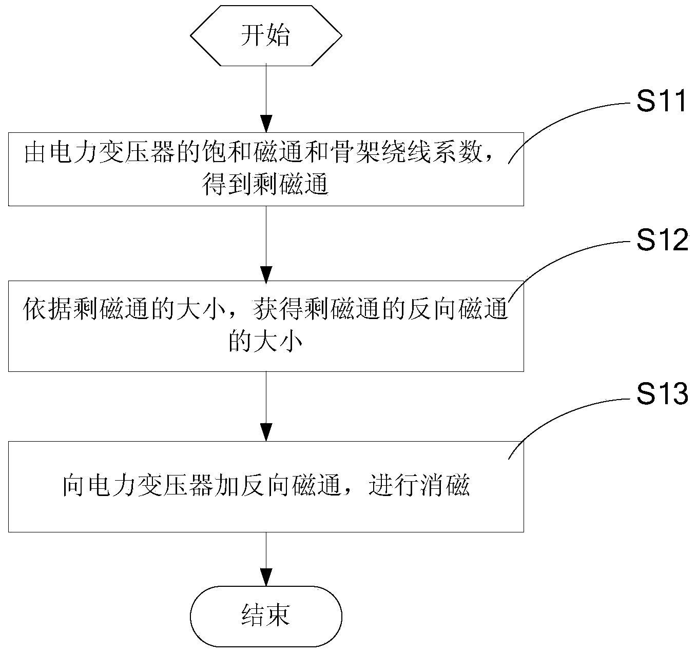
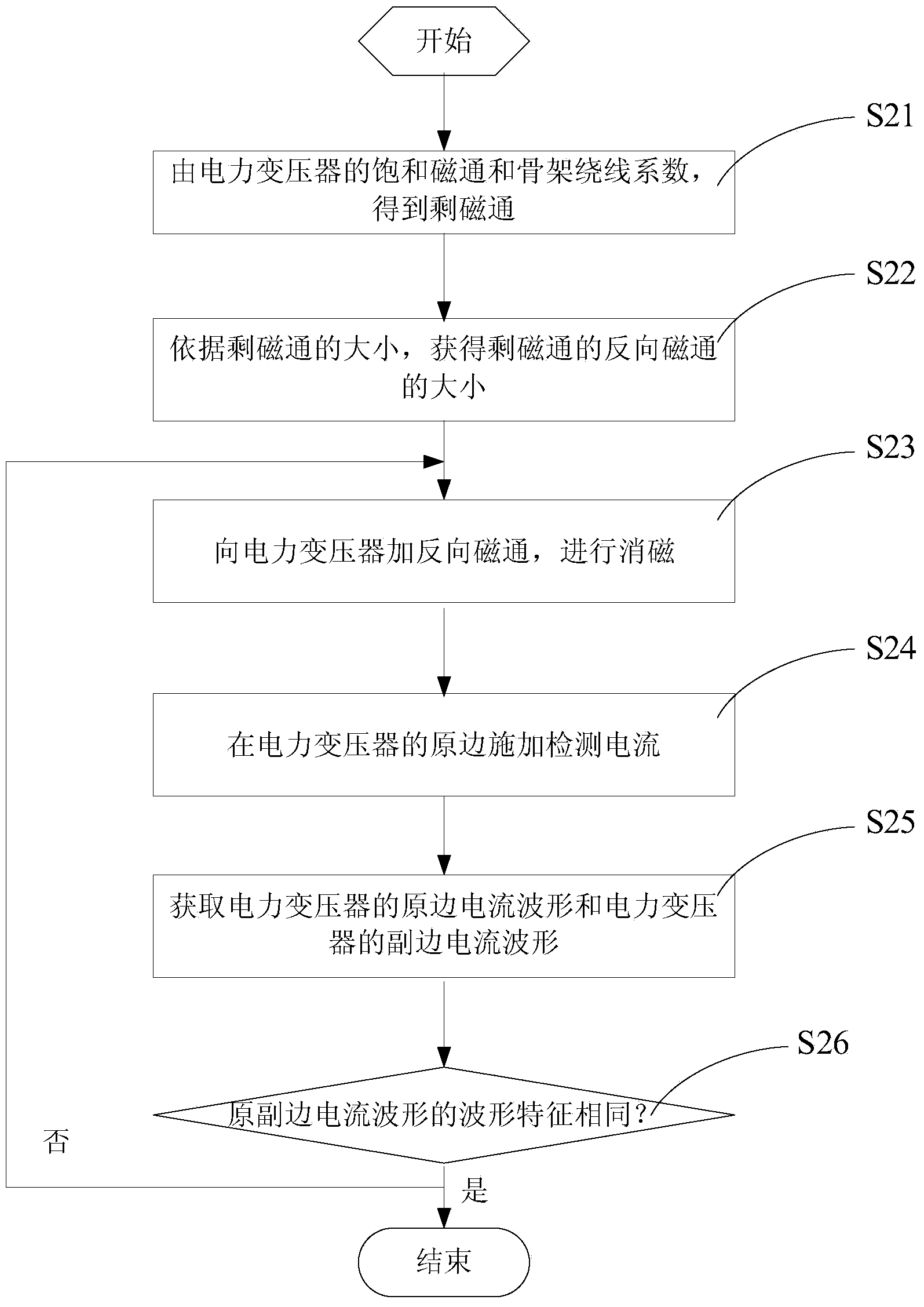
[0038] see figure 1 , the embodiment of the present invention discloses a flow chart of a method for degaussing a power transformer, the method comprising steps:

[0039] S11. After the direct resistance test of the power transformer, the residual magnetic flux of the power transformer is obtained from the saturation flux of the power transformer and the winding coefficient of the skeleton;

[0040] Wherein, the polarity of the residual magnetic flux is the same a...


PUM


Abstract

The invention provides a method and a system for degaussing a power transformer. According to the method, after direct resistance of the power transformer is tested, a residual magnetic flux of the power transformer is obtained by a saturated magnetic flux and framework wire wrapping coefficients of the power transformer; a counter magnetic flux of the residual magnetic flux is obtained according to the magnitude and the polarity of the residual magnetic flux; the counter magnetic flux is added to the power transformer, and the aim of degaussing the residual magnetic flux is realized by the property that the direction of a transient state magnetic flux in the counter magnetic flux is opposite to that of the residual magnetic flux. According to the method and the system for degaussing the power transformer, the magnitude and the polarity of the residual magnetic flux in the power transformer are firstly estimated, and a counter magnetic flux technological means is added to realize effective degaussing of the residual magnetic flux; the degaussing effect is obvious, and the problems in the prior art are solved.

Description

technical field [0001] The invention relates to the technical field of power transformers, and more specifically, to a method and system for degaussing a power transformer. Background technique [0002] The power transformer is one of the important components of the power grid. After the direct resistance test of the power transformer, there will be a certain residual magnetic flux in the iron core. Due to the existence of the residual magnetic flux, a large number of harmonics will be generated in the excitation current, which not only increases the The reactive power consumption of the power transformer may also cause the malfunction of the relay protection, resulting in economic losses. At the same time, the high saturation of the iron core also increases the magnetic flux leakage, causing local overheating of the metal components of the power transformer and decomposition of the transformer oil, which affects the service life of the power transformer. And once the resid...

Claims


Application Information

Patent Timeline
IPC IPC(8): H01F13/00
Inventor 林磊陈水耀肖远清孙林涛李显鹏周建平张恒祥宋小舟郑涛
Owner STATE GRID CORP OF CHINA
Why Eureka
Try Eureka