Electroplating device

An electroplating device and electroplating box technology, applied in the electrolysis process, electrolysis components, cells, etc., can solve the problems of forming impurities and affecting the quality of electroplating processing, etc., and achieve the effects of sufficient electromagnetic conversion, prolonging the vibration time, and saving time

Pending Publication Date: 2021-02-05
陈虎
View PDF1 Cites 0 Cited by
  • Summary
  • Abstract
  • Description
  • Claims
  • Application Information

AI Technical Summary

Problems solved by technology

[0006] Aiming at the deficiencies of the prior art, the present invention provides an electroplating device, which solves the problem that in the electroplating process, due to the replacement of elements in the electroplating solution, the elements are aggregated to form element particles and form impurities, which have a negative effect on the electroplating solution. The problem of partitioning and affecting the processing quality of electroplating

Method used


Image

  • Electroplating device
  • Electroplating device
  • Electroplating device

Examples


Embodiment

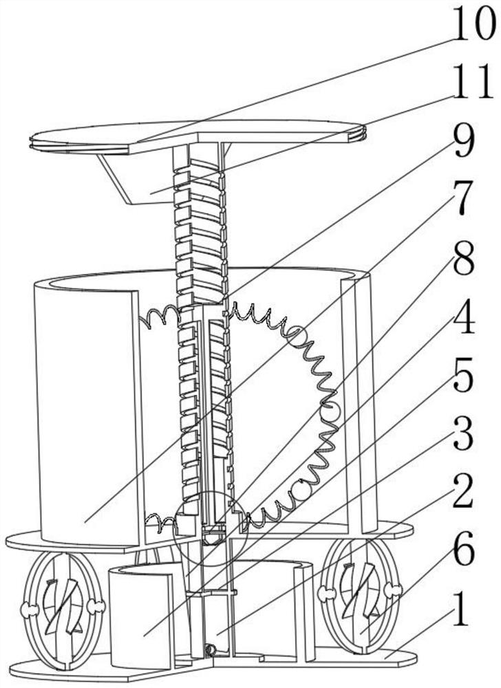
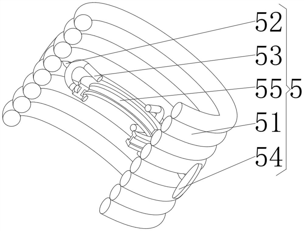
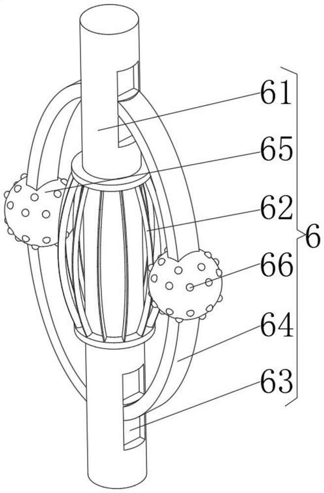
[0039] see Figure 1-5, the present invention provides a technical solution: an electroplating device, including a placement bottom plate 1, a backflow cavity tube 2 fixedly connected to the middle position of the top of the bottom plate 1, a filter core tube 3 movably connected to the top of the backflow cavity tube 2, and an outer side of the backflow cavity tube 2 The front of the surface and the bottom of the back are connected with a return pipe 4, and the top of the bottom plate 1 is located outside the return cavity tube 2 and is fixedly connected with a magnetic control mechanism 5, and the top of the bottom plate 1 is located on the side of the magnetic control mechanism 5 away from the return cavity tube 2. Mechanism 6, the trigger mechanism 6 is movably connected with an electroplating box 7 on the side away from the bottom plate 1, and a pressure applying mechanism 8 is arranged at the middle of the bottom of the inner cavity of the electroplating box 7, and the bot...


PUM


Abstract

The invention discloses an electroplating device. The electroplating device comprises a placement bottom plate, a backflow cavity pipe is fixedly connected to the middle position of the top of the placement bottom plate, a filter element pipe is movably connected to the top of the backflow cavity pipe, and backflow pipes communicate with the bottoms of the front face and the back face of the outersurface of the backflow cavity pipe. A magnetic control mechanism is fixedly connected to the position, located on the outer side of the backflow cavity pipe, of the top of the placement bottom plate, a trigger mechanism is movably connected to the side, away from the backflow cavity pipe, of the magnetic control mechanism and on the top of the placement bottom plate, and an electroplating box ismovably connected to the side, away from the placement bottom plate, of the trigger mechanism. A pressure applying mechanism is arranged at the middle position of the bottom of an inner cavity of theelectroplating box, an inner regulation and control mechanism is movably connected to the position, located on the outer side of the pressure applying mechanism, of the bottom of the inner cavity ofthe electroplating box, and the electroplating device relates to the technical field of electroplating. Internal element particles are filtered through flowing filtration of internal electroplating liquid, so that simultaneous electroplating replacement of the internal element particles of the equipment and a machined part is avoided, normal electroplating is guaranteed, and the machining qualityand efficiency are guaranteed.

Description

technical field [0001] The invention relates to the technical field of electroplating, in particular to an electroplating device. Background technique [0002] Electroplating refers to a surface processing method that uses an electrolytic device to reduce the anode metal ions in the salt electroplating solution including the anode metal to simple metal by using the principle of oxidation-reduction reaction, and deposit the simple metal on the surface of the workpiece to be electroplated to form a coating. [0003] According to the Chinese patent CN207468763U, the mobile stirring electroplating device moves the workpiece to be plated vertically and / or horizontally, so that the workpiece moves in a circle relative to the fixed nozzle, so that the coating of the workpiece cannot form uneven coatings, and individual The brightness between electroplating areas is consistent, greatly improving the quality of electroplating, and the structure is simple. During the electroplating p...

Claims


Application Information

Patent Timeline
IPC IPC(8): C25D17/00C25D21/10C25D21/06C25D21/12
CPCC25D17/00C25D21/06C25D21/10C25D21/12
Inventor 陈虎
Owner 陈虎
Why Eureka
Try Eureka