
Hybrid integrated optical sub-assembly

An optical sub-module and integrated technology, which is applied in optics, optical components, light guides, etc., can solve problems such as difficulty in inserting multi-source protocols and excessive volume of optical transceiver modules

Inactive Publication Date: 2017-01-04
ELASER TECH
View PDF6 Cites 4 Cited by
  • Summary
  • Abstract
  • Description
  • Claims
  • Application Information

AI Technical Summary

Problems solved by technology

[0004] Since the volume of the components will increase after packaging, the optical transceiver module assembled from the above-mentioned packaged components is usually too large to be placed in a small case that complies with the industry's Multi-Source Agreement (MSA). Inside

Method used


Image

  • Hybrid integrated optical sub-assembly
  • Hybrid integrated optical sub-assembly
  • Hybrid integrated optical sub-assembly

Examples


Embodiment Construction

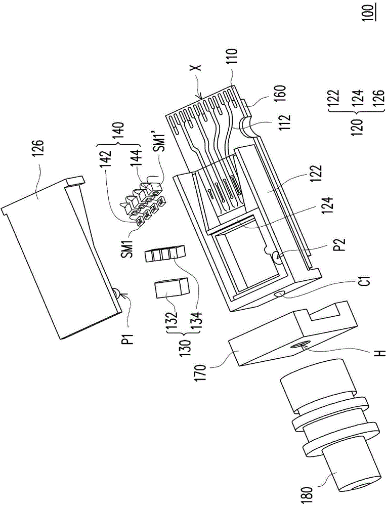
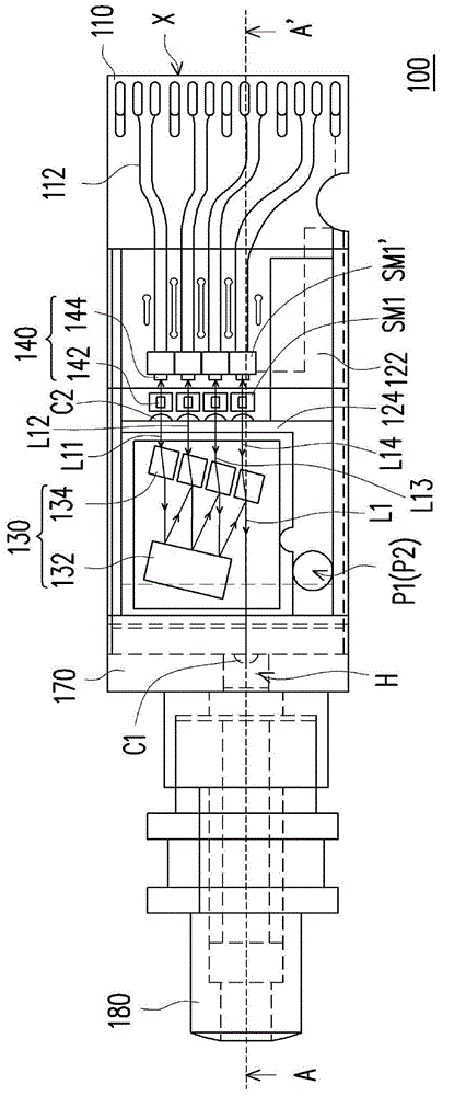
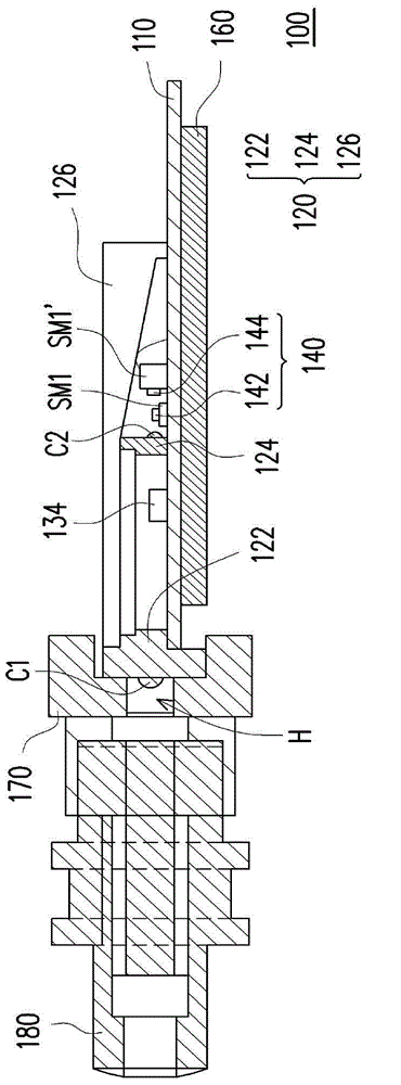
[0089] Figure 1A is an exploded view of a hybrid integrated optical sub-module according to the first embodiment of the present invention. Figure 1B yes Figure 1A The schematic diagram of the top view, where Figure 1B omitted to show Figure 1A The upper cover in , to clearly indicate the components located under the upper cover. Figure 1C is along Figure 1B Schematic cross-sectional view of the middle section line A-A'. Please refer to Figure 1A to Figure 1C , the hybrid integrated optical sub-module 100 includes a substrate 110 , a casing 120 , an optical processing unit 130 and a plurality of photoelectric conversion components 140 .

[0090] The substrate 110 is a printed circuit board, a ceramic substrate, a metal composite substrate, or other substrates suitable for carrying components and providing wiring. The ceramic substrate may be an aluminum oxide substrate or an aluminum nitride substrate. Circuits 112 for transmitting signals (such as electrical signal...


PUM


Abstract

A hybrid integrated optical sub-assembly including a substrate, a shell, an optical processing unit, and a plurality of photoelectric conversion elements is provided. The shell is disposed on the substrate and includes a frame and a beam connected to the frame. The frame has at least one first lens element, and the beam has at least one second lens element. The optical processing unit is located between the at least one first lens element and the at least one second lens element. The photoelectric conversion elements are disposed on the substrate, and the at least one second lens element is located between the optical processing unit and the photoelectric conversion elements. The invention can reduce the size of the optical sub-assembly.

Description

technical field [0001] The invention relates to an optical sub-module, in particular to a hybrid integrated optical sub-module. Background technique [0002] With the advancement of communication technology, communication methods are no longer limited to the use of electrical signals. Recently, an optical communication technology that uses optical signals to realize signal transmission has been developed. Since the transmission rate and distance of light are much higher than that of electrons, optical communication has gradually become the mainstream of the market. [0003] Based on the demand for high bandwidth, the demand for optical transceiver modules capable of transmitting a large number of optical signals is increasing day by day. The optical transceiver module is mainly composed of a plurality of photoelectric conversion components, a plurality of optical components and a circuit board. Generally speaking, the photoelectric conversion component will first be packa...

Claims


Application Information

Patent Timeline
Patent Type & Authority Applications(China)
IPC IPC(8): G02B6/42
CPCG02B6/4204G02B6/426G02B6/428G02B6/4285G02B6/4286G02B6/4206G02B6/4215G02B6/4278G02B6/4246
Inventor 郑祝良
Owner ELASER TECH
Learn More